Table of Contents
The 2013 Infiniti Q premium sedan was unveiled at the Detroit Auto Show, the first model to be named after the brand's changed naming strategy. The Q replaces the Infiniti G series and embodies the company's new design direction.

Considered fuse diagrams Infiniti Q50 / Q60 (V36) 2013, 2014, 2015, 2016 year of release.
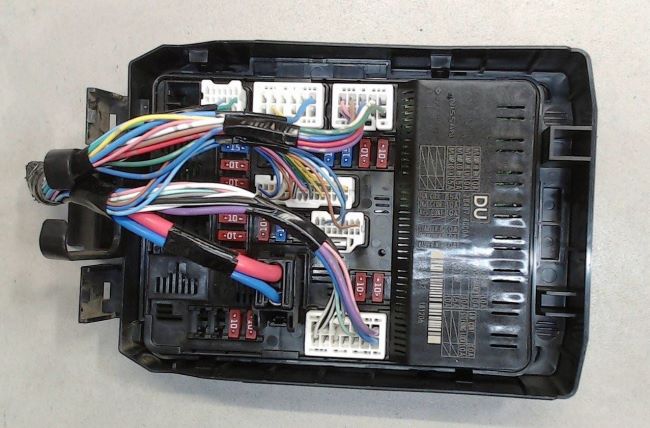
In the engine compartment

There are two boxes and one power board on the battery.
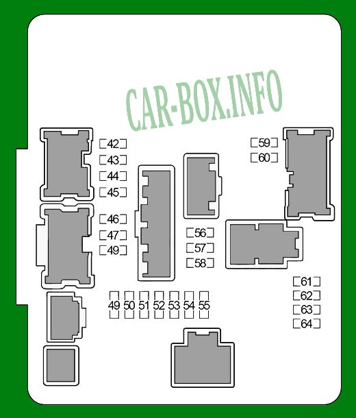
Fuse box #1
General form.
| Diagram | ||
|---|---|---|
|
||
| No. | Decoding | A |
| 42 | Right headlight (high beam) | 10 |
| 43 | Left headlight (high beam) | 10 |
| 44 | Right headlight (low beam) | 15 |
| 45 | Left headlight (low beam) | 15 |
| 46 | Engine control module (ECM), MAF sensors, EVAP | 10 |
| 47 | Evaporative emission (EVAP) system, intake phase control solenoid valve, variable valve timing (VVEL) | 10 |
| 48 | Air fuel ratio sensors, oxygen sensors | 15 |
| 49 | Ignition coils, capacitor | 15 |
| 50 | Injectors, engine control module (ECM) | 10 |
| 51 | Transmission control module (TCM) | 10 |
| 52 | Fuel pump relay | 15 |
| 53 | Cooling fan relay # 1 | 10 |
| 54 | ABS, Intelligent Cruise Control (ICC), Accelerator Pedal Position Sensor, Steering Angle Sensor, | 10 |
| 55 | Windshield washer pump | 10 |
| 56 | Wiper relay | 30 |
| 57 | Front fog light relay | 15 |
| 58 | Daytime running light relay | 10 |
| 59 | Side light (left side) | 10 |
| 60 | Side light (right side), interior lighting, trunk lock | 10 |
| 61 | Air conditioner relay | 10 |
| 62 | - | - |
| 63 | Throttle valve relay | 15 |
| 64 | Engine control unit (ECM) | 10 |
Fuse box #2
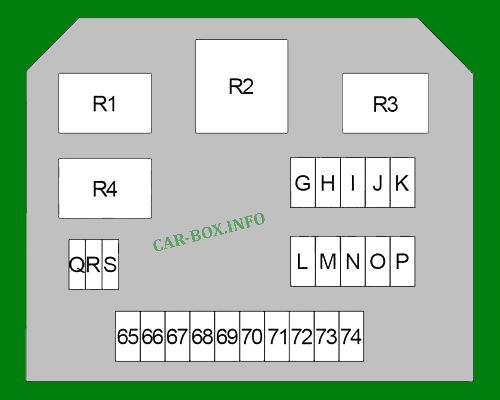
Diagram.
| No. | Decoding | A |
| 65 | Anti-theft horn relay | 10 |
| 66 | Horn relay | 15 |
| 67 | Accelerator Pedal Position Sensor, Intelligent Cruise Control (ICC) | 10 |
| 68 | Transmission control module (TCM) | 10 |
| 69 | Generator | 10 |
| 70 | All-wheel drive control unit (AWD) | 10 |
| 71 | - | - |
| 72 | Daytime running light relay | 10 |
| 73 | 10 | |
| 74 | - | - |
| G | Direct Adaptive Steering: Power steering control unit | 60 |
| H | Direct Adaptive Steering: Additional steering wheel control unit | 100 |
| I | - | - |
| J | Direct Adaptive Steering: Steering wheel control unit | 100 |
| K | - | - |
| L | ABS | 30 |
| M | Body Electronics Module (BCM), Circuit Breaker (Driver's Seat Adaptation System, Power Seat) | 40 |
| N | ABS | 50 |
| O | Cooling fan relay # 1 | 50 |
| P | Variable valve timing system (VVEL) | 50 |
| Q | Pre-crash belt tensioner system (passenger side)) | 30 |
| R | Ignition relay (fuses "11", "12", "13", "14", "22") | 30 |
| S | Pre-crash seat belt pretensioner system (driver's side) | 30 |
| Relay | ||
| R1 | Sound signal | |
| R2 | Cooling system fan No. 1 | |
| R3 | Daytime Running Lights | |
| R4 | Anti-theft alarm sound | |
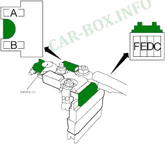
Power fuse panel
Located on the battery.
| Diagram | ||
|---|---|---|
|
||
| No. | Description | A |
| A | Starter, alternator, fuses "E", "D", "C" | 250 |
| B | - | - |
| F | High beam relay (fuses "42", "43"), low beam relay (fuses "44", "45"), side light relay (fuses "59", "60"), fuses "56", " 57 "," 58 " | 60 |
| E | Auxiliary relay (Power Socket Relay, fuses "1"), socket relay (fuses "25"), heated rear window relay (fuses "8", "9", "10"), heater relay (fuses "27", " 28 "), fuses" 2 "," 3 "," 4 "," 5 "," 6 "," 7 "," 15 "," 17 "," 19 "," 20 "," 30 "," 32 "," 33 "," 36 " | 100 |
| D | Relay engine control unit (ECM) (fuses "46", "47", "48"), ignition relay (fuses "49", "50", "51", "52", "53", "54", "55"), fuses "61", "63", "64" | 80 |
| C | Fuses "65", "66", "67", "68", "69", "70", "72", "73", "G", "H", "J", "L", " M "," N "," O "," P "," Q "," R "," S " | 100 |
In the passenger compartment
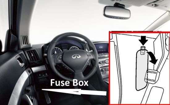
Fuse box located at the driver's feet at the bottom behind a plastic cover.
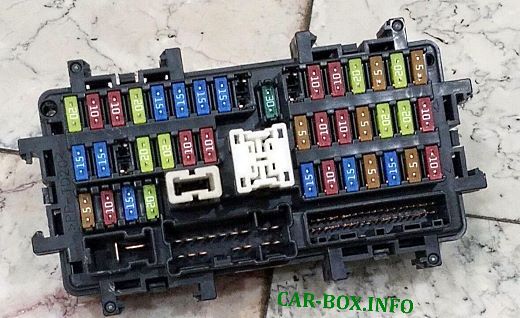
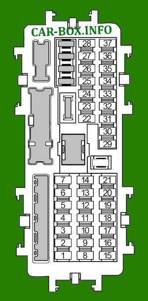
General view of the block.
| Diagram | ||
|---|---|---|
|
||
| No. | Decoding of fuses | A |
| 1 | Instrument cluster, surround view system, air conditioning amplifier, BOSE amplifier, telematics control unit (TCU), power windows, display control unit, navigation, AV module | 10 |
| 2 | Body Electronics Module (BCM) | 5 |
| 3 | Amplifier BOSE | 15 |
| 4 | Pre-crash belt pretensioner system, diagnostic socket, electrochromic rearview mirror, rain sensor, smart key system buzzer | 5 |
| 5 | Amplifier BOSE | 15 |
| 6 | A / C amplifier, start button, instrument cluster | 10 |
| 7 | Display Control Unit, Telematics Control Unit (TCU), AV Module, Navigation, Surround View System | 15 |
| 8 | Heated mirrors | 10 |
| 9 | Heated rear window | 20 |
| 10 | Heated rear window | 20 |
| 11 | Reversing lamp relay, instrument cluster | 5 |
| 12 | Selector lever lock relay, headlight range control, air pollution sensor, adaptive lighting system (AFS), brake pedal position sensor, brake light switch, chassis control unit, compressor, Direct Adaptive Steering, power steering control unit, air conditioning amplifier , navigation, ionizer, high beam control unit, electrochromic rearview mirror, diagnostic socket | 10 |
| 13 | Airbags | 10 |
| 14 | Display Control Unit, Parktronic, Telematics Control Unit (TCU), Surround View System, Heated Seat Relay, Can Bus, Lane Follower, Adaptive Lighting System (AFS) | 5 |
| 15 | Driver's seat adaptation, Meter Control Switch, gear selector, glove box lighting, seat memory, combination switch, telematics control unit (TCU) | 5 |
| 16 | - | - |
| 17 | Keyless Entry Receiver, AWD Control Module, Can Bus | 5 |
| 18 | - | - |
| 19 | Brake Light Switch, Body Electronics Module (BCM), Intelligent Cruise Control (ICC) | 10 |
| 20 | Body Electronics Module (BCM) | 10 |
| 21 | - | - |
| 22 | Driver Assistance System (ADAS), Warning Buzzer, All-Wheel Drive Control Module (AWD) | 10 |
| 23 | - | - |
| 24 | - | - |
| 25 | 12V Socket #1, 12V socket #2 (Infinity Q50 / Q60 cigar lighter fuse) | 20 |
| 26 | - | - |
| 27 | Heater motor | 15 |
| 28 | Heater motor | 15 |
| 29 | - | - |
| 30 | Body electronics module (BCM), driver's seat adaptation system | 15 |
| 31 | - | - |
| 32 | Seat heating relay | 15 |
| 33 | Body Electronics Module (BCM) | 15 |
| 34 | - | - |
| 35 | - | - |
| 36 | Steering wheel heater relay | 10 |
| 37 | - | - |

|
|
| No. | Relay |
| R1 | Heated rear window |
| R2 | Auxiliary relay |
| R3 | 12V Power Sockets |
| R4 | Ignition |
| R5 | Heater |
