A4 (B8) is the fourth generation of the mid-size sedan and station wagon of the German company Audi. This generation was produced from 2007 to 2015. Restyling took place in 2011. In this material, we will analyze in detail the fuse diagrams of the Audi A4 (B8) of the 4th generation: 2007, 2008, 2009, 2010, 2011 and 2012, 2013, 2014, 2015 release.
Here you will find the locations and photos of the mounting blocks. Separately, we note the fuses responsible for the cigarette lighter and fuel pump.
In the luggage compartment
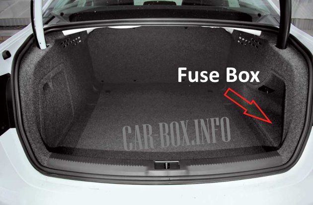
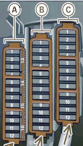
The block is located on the right side of the trunk, behind the trim panel.
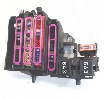
General form.
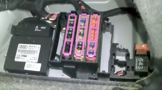
Access example.
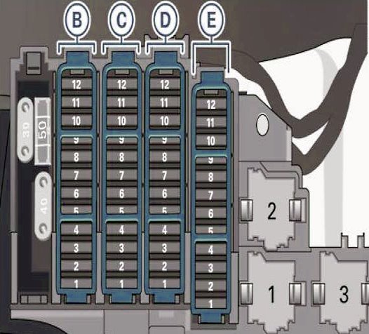
| Diagram (2007 - 2011 model year) | ||
|---|---|---|

|
||
| Models 2007 - 2009 | ||
| No. | A | Purpose |
| Black panel | ||
| 1 | — | — |
| 2 | 15 | trailer control unit |
| 3 | 20 | trailer control unit |
| 4 | 20 | trailer control unit |
| 5 | 5 | Electronic parking brake |
| 6 | 15 | Electronic suspension control |
| 7 | 30 | Electromechanical parking brake |
| 8 | 30 | Vehicle onboard network control unit 2 |
| 9 | — | — |
| 10 | 30 | Vehicle onboard network control unit 2 |
| 11 | 20 | Vehicle onboard network control unit 2 |
| 12 | — | — |
| Brown panel | ||
| 1 | 15 | Socket 12 V |
| 2 | — | — |
| 3 | 7.5 | Radio / navigation |
| 4 | 30 | Digital Sound System Control Unit |
| 5 | 5 | MMI |
| 6 | 30 | Door control unit (driver's side) |
| 7 | 30 | Electromechanical parking brake |
| 8 | 30 | Rear seat heating |
| 9 | 30 | Door control unit (passenger side) |
| 10 | 5 | Auxiliary heater remote control receiver |
| 11 | 15 | Door control unit (passenger side) |
| 12 | 5 | Rear view camera control unit |
| Red panel | ||
| 1 | 15 | Socket, center console, rear |
| 2 | 15 | Outlet, center console, front |
| 3 | 15 | Socket, luggage compartment |
| 4 | 15 | cigarette lighter fuse |
| 5 | 5 | Assistance with parking |
| 6 | 5 | Phone Preset without Handsfree System (VDA Interface) |
| 7 | 15 | Adaptive cruise control control unit |
| 8 | — | — |
| 9 | 5 | EPB switch (electromechanical parking brake) |
| 10 | 5 | Lane change assist function |
| 11 | 5 | Rear seat heating |
| 12 | 5 | Air bag |
| Models 2010 - 2011 | ||
| No. | A | Purpose |
| Black panel B | ||
| 1 | 30 | Trunk Lid Control Module (Avant) |
| 2 | 15 | trailer control module |
| 3 | 20 | |
| 4 | 20 | |
| 5 | 5 | Electromechanical parking brake |
| 6 | 15 | Electronic damping control |
| 7 | 30 | Electromechanical parking brake |
| 8 | 30 | Onboard supply control module 2 |
| 9 | 35 | Quattro Sport |
| 10 | 30 | Onboard supply control module 2 |
| 11 | 20 | Onboard supply control module 2 |
| 12 | 5 | Terminal 30 |
| Brown panel C | ||
| 1 | 30 | Trunk Lid Control Module |
| 2 | 15 | Heated front right seat |
| 3 | 40 | DC/DC converter path 1 |
| 4 | 40 | DC to DC converter path 2 |
| 5 | 30 | Connector |
| 6 | — | — |
| 7 | 30 | Electromechanical parking brake |
| 8 | 30 | Rear seat heating |
| 9 | 30 | Passenger side door control module |
| 10 | — | — |
| 11 | 15 | Passenger side door control module |
| 12 | — | — |
| Red panel D | ||
| 1 | 15 | Exit to the rear center console |
| 2 | 15 | Front center console socket |
| 3 | 15 | Exit from the luggage compartment |
| 4 | 15 | cigarette lighter fuse |
| 5 | 5 | V6FSI |
| 6 | 5 | Supply entertainment for rear seat passengers |
| 7 | 7.5 | parking system |
| 8 | 15 | Rear wiper (Avant) |
| 9 | 5 | Electromechanical parking brake switch |
| 10 | 5 | Audi side assistant |
| 11 | 5 | Rear seat heating |
| 12 | 5 | Terminal 15 control modules |
| Black panel E | ||
| 1 | — | — |
| 2 | — | — |
| 3 | 30 20 |
DSP amplifier, radio |
| 4 | 7.5 | MMI |
| 5 | 7.5 | Preparing for radio/navigation/cell phone |
| 6 | 5 | Rear View Camera |
| 7 | — | — |
| 8 | — | — |
| 9 | — | — |
| 10 | — | — |
| 11 | — | — |
| 12 | — | — |
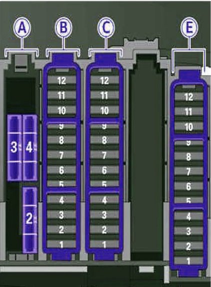
| Diagram (2011 - 2015 model year) | ||
|---|---|---|
| Models 2011 - 2013 | ||
|
||
| No. | A | Description |
| Black panel B | ||
| 1 | 30 | Trunk Lid Control Module (Avant) |
| 2 | 15 | trailer control module |
| 3 | 20 | trailer control module |
| 4 | 20 | trailer control module |
| 5 | 5 | Electromechanical parking brake |
| 6 | 15 | Electronic damping control |
| 7 | 30 | Electromechanical parking brake |
| 8 | 30 | Onboard supply control module 2 |
| 9 | 35 | Quattro Sport |
| 10 | 30 | Onboard supply control module 2 |
| 11 | 20 | On-board network control module |
| 12 | 5 | Terminal 30 |
| Brown panel C | ||
| 1 | 30 | Trunk Lid Control Module |
| 2 | 15 | Heated front right seat |
| 3 | 40 | DC/DC converter path 1 |
| 4 | 40 | DC to DC converter path 2 |
| 5 | 30 | Connector |
| 6 | — | — |
| 7 | 30 | Electromechanical parking brake |
| 8 | 30 | Rear seat heating |
| 9 | 30 | Passenger side door control module |
| 10 | — | — |
| 11 | 15 | Passenger side door control module |
| 12 | — | — |
| Red panel D | ||
| 1 | 15 | Exit to the rear center console |
| 2 | 15 | Front center console socket |
| 3 | 15 | Exit from the luggage compartment |
| 4 | 15 | Audi b8 cigarette lighter fuse |
| 5 | 5 | V6FSI |
| 6 | 5 | Supply entertainment for rear seat passengers |
| 7 | 7.5 | parking system |
| 8 | 15 | Rear wiper (Avant) |
| 9 | 5 | Electromechanical parking brake switch |
| 10 | 5 | Audi side assistant |
| 11 | 5 | Rear seat heating |
| 12 | 5 | Terminal 15 control modules |
| Black panel E | ||
| 1 | — | — |
| 2 | — | — |
| 3 | 30/20 | DSP amplifier, radio |
| 4 | 7.5 | MMI |
| 5 | 7.5 | Preparing for radio/navigation/cell phone |
| 6 | — | — |
| 7 | 5 | Cell phone preparation |
| 8 | — | — |
| 9 | — | — |
| 10 | — | — |
| 11 | — | — |
| 12 | — | — |
| Models 2014 - 2015 | ||
|
||
| No. | A | Purpose |
| Black Panel A | ||
| 1 | 30 | — |
| 2 | 30 | rear glass (cabriolet) |
| 3 | 30 | Electric top latch (Cabriolet) |
| 4 | 50 | Power top hydraulic system (convertible) |
| Black panel B | ||
| 1 | 30/10 | Trunk Lid Control Module (Universal) / Top Drive Control Module (Convertible) |
| 2 | 10 | Retractable rear spoiler (RS 5 Coupe) |
| 3 | — | — |
| 4 | — | — |
| 5 | 5 | Electromechanical parking brake |
| 6 | 15 | Electronic damping control |
| 7 | 30 | Electromechanical parking brake |
| 8 | 30 | Rear exterior lighting |
| 9 | 35 | Quattro Sport |
| 10 | 30 | Rear exterior lighting |
| 11 | 20 | central locking |
| 12 | 5 | Terminal 30 |
| Brown panel C | ||
| 1 | 30 | Trunk lid control unit (allroad) |
| 2 | 20 | 12 volt socket, cigarette lighter fuse Audi A4 |
| 3 | 40 | DCDC converter path 1 |
| 4 | 40 | DCDC converter path 2. DSP amplifier, radio |
| 5 | 30 | Heating of the right upper cab (Cabriolet) |
| 6 | — | — |
| 7 | 30 | Electromechanical parking brake |
| 8 | — | — |
| 9 | 30 | Right front door (power window, central locking, mirror, switch, lighting) |
| 10 | 30 | Heating of the left top cabin (Convertible) |
| 11 | 30 | 2-door models: right rear window regulator, 4-door models: right rear window (window regulator, central locking, switch, lighting) |
| 12 | 5 | Cell phone preparation |
| Black panel E | ||
| 1 | 15 | Heated front right seat |
| 2 | — | — |
| 3 | — | — |
| 4 | 7.5 | MMl |
| 5 | 5 | Radio |
| 6 | 5 | Rear View Camera |
| 7 | 30 | Rear window heater (allroad) |
| 8 | 5 | Rear seat multimedia |
| 9 | — | — |
| 10 | — | — |
| 11 | — | — |
| 12 | — | — |
In the passenger compartment
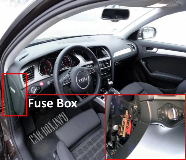
There are two mounting blocks here: one on the driver's side, the other on the passenger side.
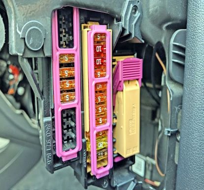
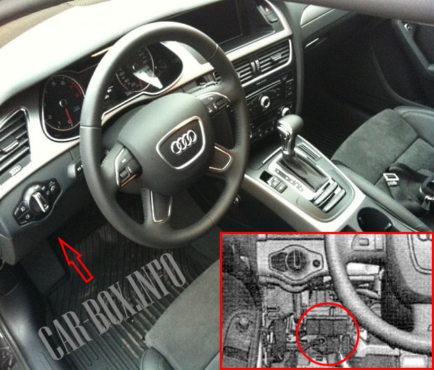
On the driver's side
The photo is an example of a driver's side block.
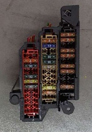
| Assigment of fuses (2007 - 2011 model year) | ||
|---|---|---|

|
||
| Models 2007 - 2009 | ||
| No. | A | Description |
| Black Panel A | ||
| 1 | 5 | Dynamic Steering |
| 2 | 5 | clutch sensor |
| 3 | 5 | Garage door opener |
| 4 | 10 | Audi lane assist |
| 5 | 5 | Air conditioning |
| 6 | 5 | Headlight beam leveler (right) |
| 7 | 5 | Headlight range control (left) |
| 8 | 5 | Vehicle onboard network control unit 1 |
| 9 | 5 | Interior mirrors |
| 10 | 5 | selector valve |
| 11 | 5 | Heated washer jets |
| 12 | 5 | Air conditioning |
| Brown panel B | ||
| 1 | — | — |
| 2 | 5 | clutch sensor |
| 3 | 20/25 | Fuel pump (diesel / gasoline) |
| 4 | 5 | Auxiliary water pump (3.2 FSI) |
| 5 | 30 | Seat heating (left) with / without seat ventilation |
| 6 | 10 | Electronic stabilization program |
| 7 | 25 | Horn |
| 8 | 30 | Power window motor (left door) |
| 9 | 30 | wiper motor |
| 10 | 25 | Electronic stabilization program |
| 11 | 15 | Door control unit (driver's side) |
| 12 | 5 | Rain and light sensor |
| Red Panel C | ||
| 1 | — | — |
| 2 | — | — |
| 3 | 10 | Lumbar support |
| 4 | 35 | Dynamic Steering |
| 5 | 5 | Inner Light |
| 6 | 35 | Vehicle onboard network control unit 1 |
| 7 | 30 | Vehicle onboard network control unit 1 |
| 8 | 30 | Vehicle onboard network control unit 1 |
| 9 | 20 | Panoramic tilt roof / sunroof |
| 10 | 30 | Vehicle onboard network control unit 1 |
| 11 | — | — |
| 12 | 5 | Comfort electronics |
| Models 2010 - 2011 | ||
| No. | A | Purpose |
| Black Panel A | ||
| 1 | 5 | Dynamic Steering |
| 2 | — | — |
| 3 | 5 | homelink |
| 4 | — | — |
| 5 | 5 | climate control |
| 6 | 5 | Adjusting the angle of the right headlight |
| 7 | 5 | Adjusting the angle of the left headlight |
| 8 | 5 | Onboard supply control module 1 |
| 9 | 5 | Adaptive cruise control |
| 10 | 5 | Shift gate |
| 11 | 5 | Heater washer jets |
| 12 | 5 | climate control |
| 13 | 5 | Cell phone preparation |
| 14 | 5 | Air bag |
| 15 | 25 | Terminal 15 |
| 16 | 40 | Terminal 15 motor |
| Brown panel B | ||
| 1 | 5 | Auto-dimming rearview mirror |
| 2 | 5 | clutch sensor |
| 3 | 25 | petrol fuel pump |
| 4 | 5 | Auxiliary water pump 3.2L FSI |
| 5 | 15/30 | Left seat heating with / without seat heating |
| 6 | 10 | Electronic stabilization program |
| 7 | 25 | Horn |
| 8 | 30 | Power window motor, left door |
| 9 | 30 | wiper motor |
| 10 | 25 | Electronic stabilization program |
| 11 | 15 | Left door |
| 12 | 5 | Rain and light sensor |
| Red Panel C | ||
| 1 | — | — |
| 2 | — | — |
| 3 | 10 | Lumbar support |
| 4 | 35 | Dynamic Steering |
| 5 | 5 | Climate cup holder |
| 6 | 35 | Onboard supply control module 1 |
| 7 | 20 | Onboard supply control module 1 |
| 8 | 30 | Onboard supply control module 1 |
| 9 | 20 | Panoramic sunroof |
| 10 | 30 | Onboard supply control module 1 |
| 11 | 20 | Panoramic sunroof |
| 12 | 5 | Comfort electronics |
| Assigment of fuses (2011 - 2015 model year) | ||
|---|---|---|
|
||
| Models 2011 - 2013 | ||
| No. | Purpose | A |
| Black Panel A | ||
| 1 | Dynamic Steering | 5 |
| 2 | — | — |
| 3 | homelink | 5 |
| 4 | — | — |
| 5 | climate control | 5 |
| 6 | Adjusting the angle of the right headlight | 5 |
| 7 | Adjusting the angle of the left headlight | 5 |
| 8 | Onboard supply control module 1 | 5 |
| 9 | Adaptive cruise control | 5 |
| 10 | Shift gate | 5 |
| 11 | Heater washer jets | 5 |
| 12 | climate control | 5 |
| 13 | Cell phone preparation | 5 |
| 14 | Air bag | 5 |
| 15 | Terminal 15 | 25 |
| 16 | Terminal 15 motor | 40 |
| Brown panel B | ||
| 1 | Auto-dimming rearview mirror | 5 |
| 2 | clutch sensor | 5 |
| 3 | petrol fuel pump | 25 |
| 4 | — | — |
| 5 | Left seat heating with / without seat heating | 15/30 |
| 6 | Electronic stabilization program | 10 |
| 7 | Sound signal | 25 |
| 8 | Power window motor, left door | 30 |
| 9 | wiper motor | 30 |
| 10 | Electronic stabilization program | 25 |
| 11 | Left door | 15 |
| 12 | Rain and light sensor | 5 |
| Red Panel C | ||
| 1 | — | — |
| 2 | — | — |
| 3 | Lumbar support | 10 |
| 4 | Dynamic Steering | 35 |
| 5 | Antenna | 5 |
| 6 | Onboard supply control module 1 | 35 |
| 7 | Onboard supply control module 1 | 20 |
| 8 | Onboard supply control module 1 | 30 |
| 9 | sunroof | 20 |
| 10 | Onboard supply control module 1 | 30 |
| 11 | Hatch Shadow (Avant) | 20 |
| 12 | Comfort electronics | 5 |
| Models 2014 - 2015 | ||
| No. | Purpose | A |
| Black Panel A | ||
| 1 | Dynamic Steering | 5 |
| 2 | Electronic stabilization control (module) | 5 |
| 3 | A/C system pressure sensor, electromechanical parking brake, Homelink. Auto-dimming interior rearview mirror, air quality/outside air sensor, electronic stabilization control (button) | 5 |
| 4 | — | — |
| 5 | sound drive | 5 |
| 6 | Headlight range adjustment / head light (corner light) | 5 / 7.5 |
| 7 | Headlight (turning light) | 7.5 |
| 8 | Control modules (electromechanical parking brake, shock absorber, quattro sport), DCDC converter | 5 |
| 9 | Adaptive cruise control | 5 |
| 10 | Shift/Clutch Door Sensor | 5 |
| 11 | Lateral assistance | 5 |
| 12 | Headlight range adjustment, parking system | 5 |
| 13 | Air bag | 5 |
| 14 | Rear wiper (allroad) | 15 |
| 15 | Auxiliary fuse (dashboard) | 10 |
| 16 | Auxiliary fuse terminal 15 (engine area) | 40 |
| Brown panel B | ||
| 1 | — | — |
| 2 | Stop light sensor | 5 |
| 3 | Gasoline pump | 25 |
| 4 | clutch sensor | 5 |
| 5 | Left seat heating with / without seat ventilation | 15/30 |
| 6 | Electronic stabilization control (electric) | 5 |
| 7 | Sound signal | 15 |
| 8 | Front left door (power window, central locking, mirror, switch, lighting) | 30 |
| 9 | Windshield wiper motor | 30 |
| 10 | Electronic stabilization control (valves) | 25 |
| 11 | Two-door models: rear left window regulator, Four-door models: rear left door (window regulator, central locking, switch, lighting) | 30 |
| 12 | Rain and light sensor | 5 |
| Red Panel C | ||
| 1 | — | — |
| 2 | — | — |
| 3 | Lumbar support | 10 |
| 4 | Dynamic Steering | 35 |
| 5 | Interior lighting (Convertible) | 5 |
| 6 | Windshield washer, headlight washer | 35 |
| 7 | Onboard supply control module 1 | 20 |
| 8 | 30 | |
| 9 | Power window motor, left (convertible) / sunroof | 7.5 / 20 |
| 10 | Onboard supply control module 1 | 30 |
| 11 | Sunblind Motor, Right Rear Window Lift (Convertible) | 7.5 / 20 |
| 12 | Theft warning system | 5 |
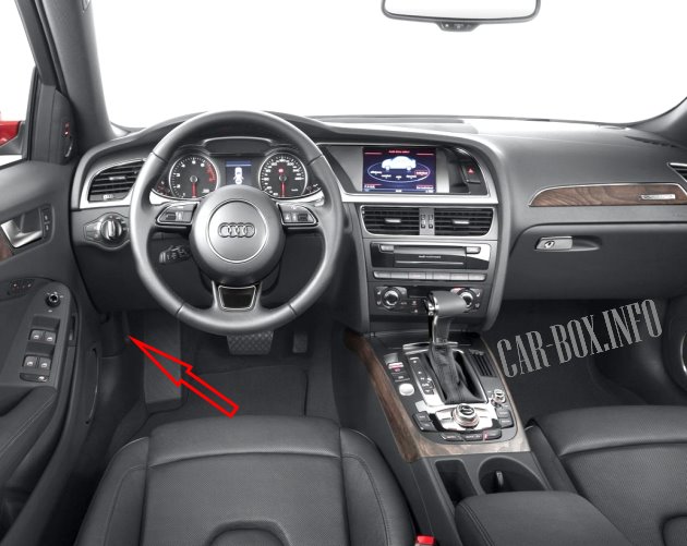
On the passenger's side
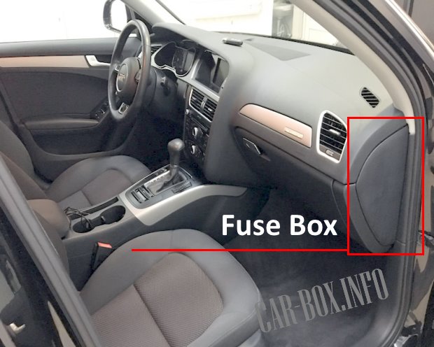
At the end of the dashboard on the passenger side is another block.
Example of access to the passenger block.
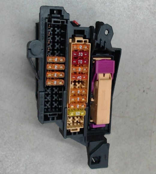
General form.
| Diagram (2007 - 2011 model year) | ||
|---|---|---|
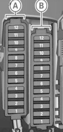
|
||
| Models 2007 - 2009 | ||
| No. | A | Purpose |
| Back panel | ||
| 1 | — | — |
| 2 | — | — |
| 3 | — | — |
| 4 | — | — |
| 5 | 5 | Steering column switch module |
| 6 | 5 | Electronic stabilization program |
| 7 | 5 | Diagnostic connector |
| 8 | 5 | Gateway (diagnostic interface for data bus) |
| 9 | — | — |
| 10 | — | — |
| 11 | — | — |
| 12 | — | — |
| Brown panel | ||
| 1 | 5 | CD drive |
| 2 | 5 | Switching module for Audi drive select |
| 3 | 10/20 | MMI / Radio |
| 4 | 5 | Switch |
| 5 | 5 | Instrument cluster control unit |
| 6 | 5 | Egnition lock |
| 7 | — | — |
| 8 | 40 | air conditioner fan |
| 9 | 5 | Steering column lock |
| 10 | 10 | Air conditioning |
| 11 | 10 | Diagnostic connector |
| 12 | 5 | Steering column switch module |
| Models 2010 - 2011 | ||
| No. | A | Purpose |
| Black panel | ||
| 1 | — | — |
| 2 | — | — |
| 3 | — | — |
| 4 | — | — |
| 5 | 5 | Steering column switch module |
| 6 | 5 | Electronic stabilization program |
| 7 | 5 | Terminal 15 of the diagnostic socket |
| 8 | 5 | Gateway |
| 9 | — | — |
| 10 | — | — |
| 11 | — | — |
| 12 | — | — |
| Brown panel | ||
| 1 | 5 | CD drive |
| 2 | 5 | Audi Drive Select Switch Module |
| 3 | 5/20 | MMI / Radio |
| 4 | 5 | instrument panel |
| 5 | 5 | Gateway |
| 6 | 5 | Egnition lock |
| 7 | 5 | Rotary light switch |
| 8 | 40 | Climate control system |
| 9 | 5 | Steering column lock |
| 10 | 10 | climate control |
| 11 | 10 | Terminal 30 of the diagnostic socket |
| 12 | 5 | Steering column switch module |
| Diagram (2011 - 2015 model year) | ||
|---|---|---|

|
||
| Models 2011 - 2013 | ||
| No. | A | Description |
| Black panel A | ||
| 1 | — | — |
| 2 | — | — |
| 3 | — | — |
| 4 | — | — |
| 5 | 5 | Steering column switch module |
| 6 | 5 | Electronic stabilization program |
| 7 | 5 | Terminal 15 of the diagnostic socket |
| 8 | 5 | Gateway (data bus diagnostic interface) |
| 9 | — | — |
| 10 | — | — |
| 11 | — | — |
| 12 | — | — |
| Brown panel B | ||
| 1 | 5 | CD/DVD player |
| 2 | 5 | Audi Drive Select Switch Module |
| 3 | 5/20 | MMI / Radio |
| 4 | 5 | instrument panel |
| 5 | 5 | Gateway (instrument cluster control module) |
| 6 | 5 | Egnition lock |
| 7 | 5 | Rotary light switch |
| 8 | 40 | climate control blower |
| 9 | 5 | Steering column lock |
| 10 | 10 | climate control |
| 11 | 10 | Terminal 30 of the diagnostic socket |
| 12 | 5 | Steering column switch module |
| Models 2014 - 2015 | ||
| No. | A | Purpose |
| Black Panel A | ||
| 1 | — | — |
| 2 | — | — |
| 3 | — | — |
| 4 | — | — |
| 5 | 5 | Steering column switch module |
| 6 | — | — |
| 7 | 5 | Terminal 15 of the diagnostic socket |
| 8 | 5 | Gateway (data bus diagnostic interface) |
| 9 | 5 | Additional heater |
| 10 | — | — |
| 11 | — | — |
| 12 | — | — |
| Brown panel B | ||
| 1 | 5 | CD/DVD player |
| 2 | 5 | Wi-Fi |
| 3 | 5/20 | MMI / Radio |
| 4 | 5 | instrument panel |
| 5 | 5 | Gateway (instrument cluster control module) |
| 6 | 5 | Egnition lock |
| 7 | 5 | Switch |
| 8 | 40 | Climate control fan |
| 9 | 5 | Steering column lock |
| 10 | 10 | Climate control system |
| 11 | 10 | Terminal 30 of the diagnostic socket |
| 12 | 5 | Steering column switch module |
Under the dashboard
The onboard network control unit is located on the driver's side under the dashboard.
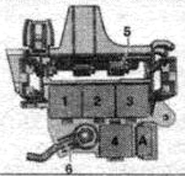
|
|
| No. | Description |
| A | ABS fuse -S123- |
| 1 | empty |
| 2 | Circulation pump relay, horn -J413-, vacuum pump -J318-, automatic dimming interior mirrors -J910- |
| 3 | Power relay cl. 15.J329- |
| 4 | Taxi anti-theft alarm remote control module -J601- |
The 6-pin switch box is located on the pillar behind the side trim in the driver's footwell.
|
||
| No. | Description | A |
| F | Thermal fuse, front passenger seat | 15 |
| G | Driver's seat thermal fuse | 15 |
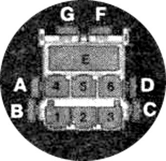
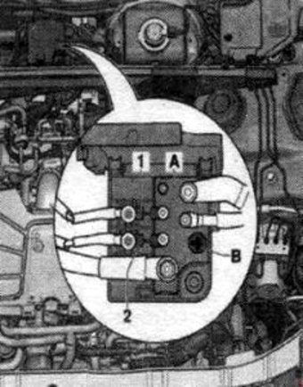
In the engine compartment

Switching box #1 is located on the left side of the engine compartment. Panel #2 is located in the center of the drainage box.
| Diagram of the switching box #1 | ||
|---|---|---|

|
||
| No. | Description (2007-2011 model year) | A |
| 1 | Automatic transmission control unit. Mechatronics for dual clutch gearboxes | 15 |
| 2 | Engine oil level and temperature sensor | 5 |
| 3 | Engine control unit. Air mass meter | 5 |
| 4 | Engine control unit | 5 |
| 5 | Air flow meter. Control unit for automatic glow plugs. Secondary air pump relay. Low heating relay. High power heating relay. Boost pressure control solenoid valve. Heating resistor of the crankcase ventilation system. Solenoid valve 1 adsorber. Secondary air control valve. solenoid valve of the left electro-hydraulic engine mount. solenoid valve of the right electro-hydraulic engine mount. Intake manifold changeover valve . Air filter bypass valve -. Fuel pressure control. Fuel metering valve. Secondary air supply control valve 2-. Change-over valve for the exhaust gas recirculation cooler. Valve for reducing oil pressure. Fuel System Diagnostic Pump | 15/10/20 |
| 6 | Engine control unit | 15 |
| 7 |
|
15/10 |
| 8 | Exhaust gas recirculation cooler pump -V400-. Ignition coil 1 with output stage. Ignition coil 2 with output stage. Ignition coil 3 with output stage. Ignition coil 4 with output stage. Ignition coil 5 with output stage. Ignition coil 6 with output stage | 5/20/10 |
| 9 | Additional fuel pump relay. Heating element lambda probe 1 after the catalyst. Heating element lambda probe 2 after catalytic converter | 15/20/5 |
| 10 | Heating element of the lambda probe. Heating element lambda probe 2. Heating element lambda probe 1 after the catalytic converter | 15/10 |
| 11 | Radiator fan control unit. Control unit 2 radiator fans | 5 |
| 12 | Air flow meter. Mechatronic automatic transmission control unit for dual clutch gearboxes | 5 |
| A | Engine Component Power Relay, Used Automatic Glow Plug System | |
| B | Starter relay 2 | |
| C | Secondary air pump relay | |
| D | Motronic system power relay, Power relay cl. thirty | |
| E | Fuel pump relay, gearbox cooling circuit, power supply for engine components 2, coolant recirculation after engine shutdown | |
| F | empty | |
| No. | Description (2011-2015 model year) | A |
| 1 | Automatic transmission control unit - Mechatronic for dual clutch gearboxes | 15 |
| 2 | Engine oil level and temperature sensor | 5 |
| 3 | Engine control unit | 5 |
| 4 | 5 | |
| 5 | Air flow meter. Fuel pressure control. Fuel metering valve | 10/15 |
| 6 | Engine control unit - Injector 2 cylinders 1, 2, 3, 4 | 15 |
| 7 | actuating element 1, 2, 3, 4, 5, 6, 7, 8 of the valve timing control system. Boost pressure control solenoid valve. Solenoid valve 1 adsorber solenoid valve of the left electro-hydraulic engine support. solenoid valve of the right electro-hydraulic engine mount. Valve 1 and 2 of the variable valve timing system. Charge air recirculation valve. Fuel pressure control. | |
| 8 | NOx sensor 2. NOx sensor control unit 2 | 10/15/5 |
| 9 | Voltage regulator. Engine control unit | 5 |
| 10 | Heating element lambda probe | 15/10 |
| 11 | Radiator fan control unit | 5 |
| 12 | Automatic transmission control unit | 5 |
| 13 | empty | - |
| 14 | Power supply relay for engine components 2. Ignition coil 1 with output stage. | 5/20 |
| 15 | Power steering control unit | 5 |
| 16 | Thermostat of the parametric engine cooling system. Control unit for automatic glow plugs | 15 |
| 17 | Heating element lambda probe after the catalyst | 15 |
| A | Power supply relay for engine components | |
| B | Starter relay 2 | |
| C | Secondary air pump relay | |
| D | Motronic Power Relay | |
| E | Fuel pump relay, gearbox cooling circuit, power supply for engine components 2, coolant recirculation after engine shutdown | |
| F | empty | |
| Panel #2 | ||
|---|---|---|
|
||
| No. | Description | A |
| 1 | 400W fan control system. / 600 W | 40/60 |
| 2 | Fan control 400 watts | 40 |
