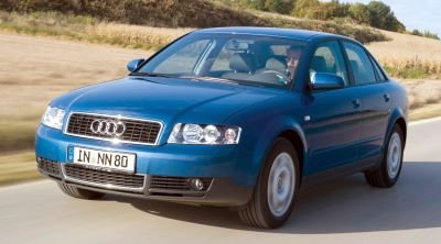
The Audi 80, since 1995 the A4, is a family of mid-range models manufactured by the German manufacturer. The internal designation of cars in this series is "type B". In this material, we will analyze in detail the fuse diagrams of the Audi A4 (B6) 2nd generation 2001, 2002, 2003, 2004, 2005 with gasoline and diesel engines.
Here you will find the locations and photos of the mounting blocks. Separately, we note the fuses responsible for the cigarette lighter and fuel pump.
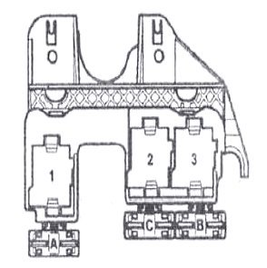
In the engine compartment
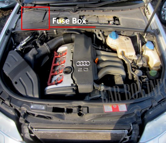
It is located on the right side of the engine compartment behind the protective lining.

Photo - an example (removed for clarity).
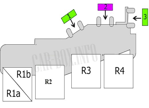
| Scheme of elements in the motor block | ||
|---|---|---|
|
||
| No. | Purpose | A |
| 1 | Engine electronics, brake pedal position sensor | 15 |
| 2 | Exhaust air pump | 40 |
| 3 | Automatic transmission | 15 |
| R1a | Automatic transmission relay | - |
| R1b | Not used | - |
| R2 | Exhaust air pump | - |
| R3 | Motronic power supply relay or main relay | - |
| R4 | Start Inhibit Switch Relay and Reverse Relay or Automatic Transmission Relay | - |
In the passenger compartment
Fuse box
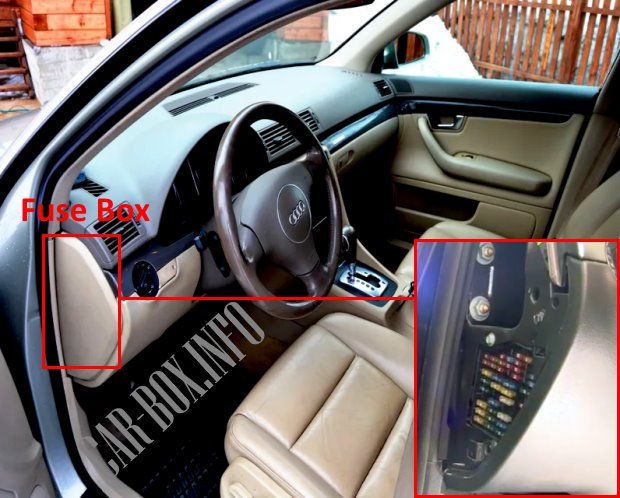
The main unit is located at the end of the dashboard behind the trim. For access, it is necessary to dismantle the lining by prying it with a screwdriver.
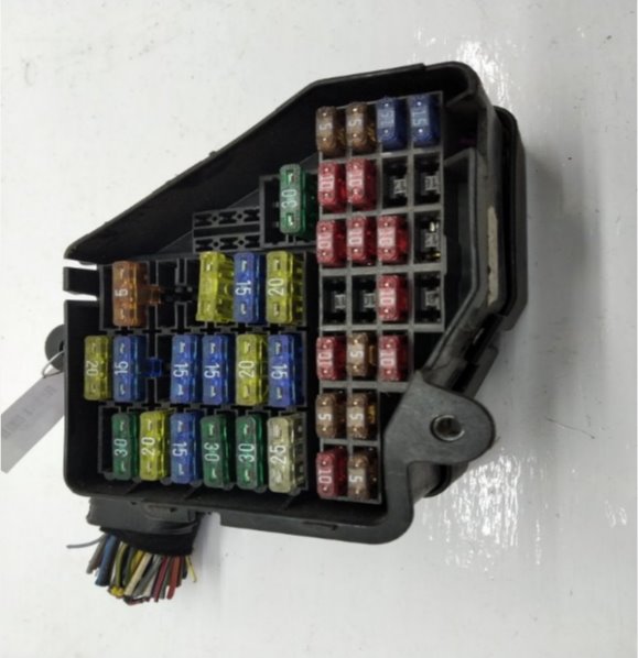
General form.
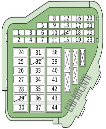
| Assigment of fuses in the Audi A4 (B6) passenger compartment | ||
|---|---|---|
|
||
| No. | Description | A |
| 1 | Air conditioning system | 10 |
| 2 | Footwell lamps, glove compartment lamp | 5 |
| 3 | Windshield washer jet heaters | 5 |
| 4 | Cooling fan motor control unit | 5 |
| 5 | Automatic transmission control system, engine oil pressure / temperature sensor, heated rear seats, navigation system, rear window sunshade drive, telephone / telematics | 10 |
| 6 | Air conditioning system | 5 |
| 7 | Anti-Lock Braking System, Stop Light Switch (Brake Pedal Position Sensor), Clutch Pedal Limit Switch (Position Sensor) | 10 |
| 8 | Telephone/telematics | 5 |
| 9 | Brake booster vacuum pump (if equipped) | 10 |
| 10 | Headlights corrector | 10 |
| 11 | Automatic transmission - 2001 | 10 |
| 12 | Diagnostic connector | 10 |
| 13 | Steering column electrical control unit | 10 |
| 14 | Stop lights | 10 |
| 15 | Instrument cluster, navigation system | 10 |
| 16 | Garage Door Remote Control System | 5 |
| 17 | parking system | 10 |
| 18 | empty | - |
| 19 | Fog lights, fog lights | 15 |
| 20 | Right headlight - dipped beam, headlight range control | 15 |
| 21 | Left headlight - low beam, headlight range control | 15 |
| 22 | Door function control unit (left front), door function control unit (left rear)(—2001) | 15 |
| 23 | Door function control unit (front right), door function control unit (rear right) (—>2001) | 15 |
| 24 | Multifunctional control unit 2-optional equipment | 20/30 |
| 25 | Air conditioner/heater fan motor | 30 |
| 26 | Rear window heater | 30 |
| 27 | Trailer control unit | 30 |
| 28 |
|
20 |
| 29 | Engine Management System - Gasoline | 20 |
| 30 | Sunroof | 20 |
| 31 | Auto-dimming interior rear-view mirror, automatic transmission control system, diagnostic socket, engine management system, reversing lights | 15 |
| 32 | Engine Management System - Gasoline | 20 |
| 33 | Audi A4 cigarette lighter fuse | 15 |
| 34 | Engine Management System - Gasoline | 15 |
| 35 | Connector for additional equipment | 30 |
| 36 | Multifunction control unit 1, windshield wiper/washer | 30 |
| 37 | Multifunction control unit 1, headlight washers | 20/25 |
| 38 | Anti-theft system, tailgate/tailgate opener, multifunctional control unit 2-accessory | 15/30 |
| 39 | Audio system, navigation system | 20/30 |
| 40 | Sound signal | 25 |
| 41 | Additional heater (2003^) | 30 |
| 42 | Anti-lock braking system, Stability Program | 25 |
| 43 | Engine Management System - Gasoline | 15 |
| 44 | Seat heaters, steering wheel heater | 30 |
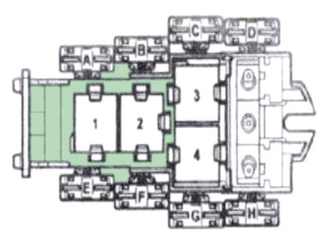
Relay blocks
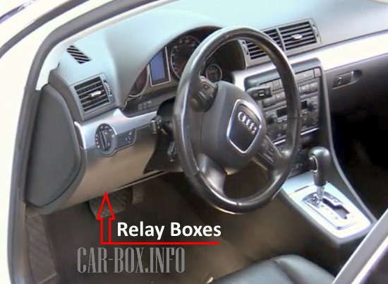
Located behind the dashboard front trim on the driver's side.
| Description of fuses and relays in relay blocks A4 B6 | ||
|---|---|---|
| Block #1 | ||
General form. |
||

diagram. |
||
| No. | Purpose | A |
| F1 | Electric rear window blind | 10 |
| F2 | 10 | |
| F3 | Not used | 3 |
| F4 | Rear power windows | 30 |
| F5 | Power seats | 10 |
| F6 | Front power windows | 30 |
| F7 | Trailer towing module | 30 |
| 1 | Fuel pump relay | - |
| 2 | Power steering | - |
| 3 | signal relay | - |
| 4 | Vacuum pump for brake booster | - |
| 5 | Not used | - |
| 6 | Auxiliary ignition circuits | - |
| 7 | Not used | - |
| 8 | - | |
| 9 | - | |
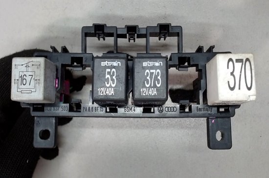
| Block #2 | ||
|
||
| No. | Protected circuits | A |
| A | Additional heater | 30 |
| C | Coolant heater | 40 |
| B | 60 | |
| 1 | empty | |
| 2 | Coolant Heater Relay 2 - High Power | |
| 3 | Coolant Heater Relay 1 - Low Power | |
| Block #3 | ||
|
||
| No. | Purpose | A |
| A | Not used | - |
| B | - | |
| C | - | |
| D | - | |
| E | Relay for turning on the fan of the cooling system | 40 |
| F | Optional equipment | 10 |
| G | Cooling fan (also used 60A) | 40 |
| H | ABS control unit | 50 |
| 1 | Not used | - |
| 2 | - | |
| 3 | - | |
| 4 | Taxi alarm control unit 3 | - |
