In 2011, BMW officially introduced the sixth generation of the 3 Series, a popular premium car. The model lineup consists of a sedan under the index F30, station wagon F31 and F34 - modification with a sloping roof. In this article we will understand in detail fuse box diagrams BMW F30 / F31 / F80 3 Series (6th Gen; 316d, 316i, 318d, 318i, 320si, 320d, 323i, 325i, 328i, 330d, 330i, 335d, 335i, Hybrid) 2011, 2012, 2013, 2013, 2014, 2015, 2015, 2016, 2017, 2018, 2019 years of manufacture.

Here you will find the locations and photos of the mounting blocks. Also, we will separately mark the fuse responsible for the cigarette lighter.
In the luggage compartment
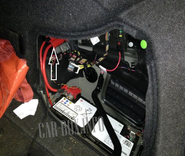
The power fusible links are located on the right side behind the case, next to the battery.
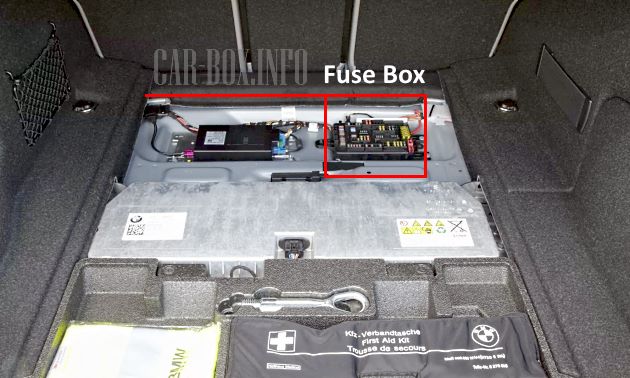
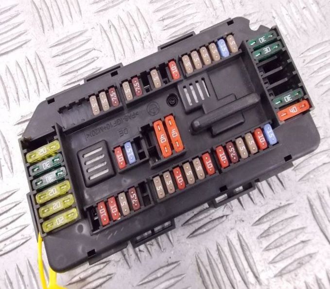
The main fuse box is in the center behind the floor pan.
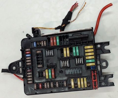
The photo is an example of the main unit.
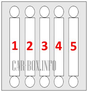
| Power block diagram (near the battery) | ||
|---|---|---|
|
||
| No. | Decryption | A |
| 1 | Rear module | 50 |
| 2 | Fuse box | 100 |
| 3 | Power distribution | 100 |
| 4 | Main relay | 125 |
| 5 | Integrated power module | 125 |
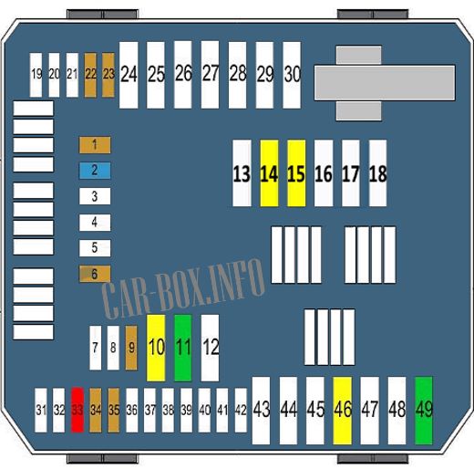
| Assigment of fuses in the luggage compartment box | ||
|---|---|---|
|
||
| No. | Decryption | A |
| 1 | Camera control unit | 5 |
| 2 | Radio control unit | 15 |
| 6 | Audio system | 5 |
| 9 | telematics | 5 |
| 10 | Radio control unit | 20 |
| 11 | hi-fi amplifier | 30 |
| 14 | Trailer towing module | 20 |
| 15 | 20 | |
| 22 | Signaling | 5 |
| Microwave sensor | ||
| 23 | remote control receiver | 5 |
| Vacuum leak detection | ||
| 33 | Audio system | 10 |
| 34 | DVD player | 5 |
| 35 | 5 | |
| 46 | End connector | 20 |
| 49 | DC-DC Converter | 30 |
In the passenger compartment
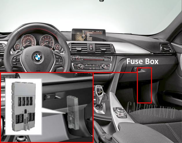
The unit is located on the passenger side on the front pillar.

General view of the BMW F30 / F31 / F80 interior fuse box.
| Diagram | ||
|---|---|---|

|
||
| No. | Description | A |
| 1 | Empty | - |
| 2 | Empty | - |
| 3 | Empty | - |
| 4 | Passenger Power Window | 30 |
| 5 | central locking system | 20 |
| 6 | Driver Power window | 30 |
| 7 | Empty | - |
| 8 | Empty | - |
| 9 | Empty | - |
| 10 | Control Panel | 5 |
| Driver assistance system | ||
| Heating, ventilation and air conditioning (HVAC) | ||
| Light switch | ||
| 11 | Rear module | 7.5 |
| Left headlight | ||
| 12 | Diagnostic connector | 7.5 |
| 13 | telematics | 5 |
| 14 | Horn (beep) | 15 |
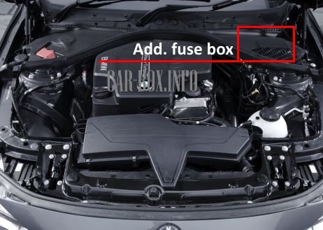
In the engine compartment
Here there are four units responsible for the protection of the vehicle's electrical circuits.
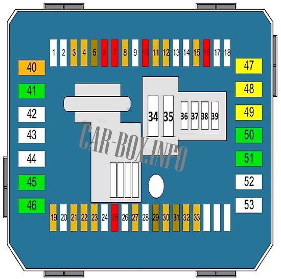
Main fuse box
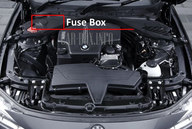
The main unit is located on the right side, closer to the windshield. To access it, you need to unscrew the mounting screws of the protective cladding. Next to it there are some relay modules and power fuses.

Access example.
General view.
| Diagram | ||
|---|---|---|
|
||
| No. | Decryption | A |
| 1 | Empty | - |
| 2 | Empty | - |
| 3 | Control unit, roof electronics | 5 |
| 4 | Heating control unit | 5 |
| 5 | Door locks | 7.5 |
| Passenger Rear View Mirror | ||
| 6 | DDE main relay | 10 |
| 7 | Electronic automatic transmission (EAT) control unit | 10 |
| 8 | touch box | 5 |
| Body control unit | ||
| 9 | Empty | - |
| 10 | Seat adjustment | 10 |
| 11 | Front left lamp | 5 |
| Front right lamp | ||
| Rain sensor | ||
| Empty | ||
| 12 | Trip relay | 5 |
| Dynamic Stability Control (DSC) | ||
| 13 | Empty | - |
| 14 | Empty | - |
| 15 | Transfer case | 5 |
| 16 | coolant pump | 10 |
| Air conditioning compressor | ||
| Additional water pump | ||
| 17 | Not | |
| 18 | Not | |
| 19 | Electrochromic rear view mirror | 5 |
| 20 | Not | - |
| 21 | Driver assistance system | 5 |
| 22 | Cruise control | 5 |
| 23 | Crankcase ventilation heater | 5 |
| Coolant shut-off valve | ||
| 24 | Empty | - |
| 25 | Steering column switches | 10 |
| 26 | Empty | - |
| 27 | instrument cluster | 5 |
| 28 | Empty | - |
| 29 | instrument cluster | 7.5 |
| 30 | Glove compartment lighting | 5 |
| 31 | selector switch | 7.5 |
| 32 | Electronic Power Steering (EPS) | 5 |
| 33 | Air quality sensor | 5 |
| 34 | Empty | - |
| 35 | Empty | - |
| 36 | Empty | - |
| 37 | Empty | - |
| 38 | Empty | - |
| 39 | Empty | - |
| 40 | Fuse box | 40 |
| 41 | Dynamic Stability Control (DSC) | 30 |
| 42 | Empty | - |
| 43 | Empty | - |
| 44 | Empty | - |
| 45 | Retractable roof | 30 |
| 46 | Transfer case | 30 |
| 47 | Passenger seat heating | 20 |
| 48 | Heated driver's seat | 20 |
| 49 | BMW F30/F31/F80 cigarette lighter fuse | 20 |
| 50 | Driver's seat control unit | 30 |
| Driver seat adjustment | ||
| 51 | Passenger seat adjustment | 30 |
| Passenger seat control unit | ||
| 52 | 12V | - |
| 53 | Empty | - |
Power fusible links
Located next to the main unit.
| Diagram | ||
|---|---|---|

|
||
| No. | Description | A |
| 1 | Cut-off relay | 50 80 125 |
| 2 | Electronic Power Steering (EPS) | 125 |
| 3 | Additional heater | 100 |
| 4 | Heated fuel filter | 40 |
| 5 | Dynamic Stability Control (DSC) | 40 |
| 6 | blower motor | 40 |
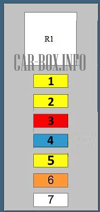
Additional panel #1
Also located next to the main unit.
| Diagram | ||
|---|---|---|
|
||
| No. | Decryption | A |
| 1 | Engine management | 20 |
| 2 | 20 | |
| 3 | 10 | |
| 4 | 15 | |
| 5 | 20 | |
| 6 | 40 | |
| 7 | coolant pump | 50 |
| R1 | Main relay DDE | |
Additional panel #2
Located on the left side of the engine compartment.
| Diagram | ||
|---|---|---|

|
||
| No. | Purpose | A |
| 1 | Ramp pressure control valve | 20 |
| Fuel volume regulator | ||
| Camshaft position sensor | ||
| Boost pressure regulator solenoid | ||
| 2 | Oxygen sensor before catalytic converter | 20 |
| Oxygen sensors behind the catalytic converter | ||
| Mass flow meter | ||
| Oil level sensor | ||
| EGR cooler changeover valve | ||
| 3 | DDE control unit | 30 |
| R1 | Main relay DDE | |

So which one is for the battery and alternator?