The sixth generation of the BMW 5-series was presented in November 2009. Henceforth, the sedan received the designation F10, station wagon F11, liftback F07. Externally, the car adheres to the accepted corporate line of the German company. It is built on the same platform as the 7-series F01. During the release period it has gone through one restyling. In this article we will understand in detail fuse box diagrams BMW F10 / F11 / F07 (5 series; 6th Gen; 518d, 520d, 520i, 523i, 525d, 528i, 530d, 530i, 535d, 535i, 550i, M5, Hybrid) 2009, 2010, 2011, 2012, 2012, 2013, 2014, 2015, 2016, 2017 years of manufacture.
Here you will find the locations and photos of the mounting blocks. Also, we will separately mark the fuses responsible for the cigarette lighter and the fuel pump.
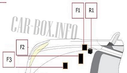
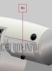
In the engine compartment

Protective elements are located on the right side. There may be DDE K2085 engine relay and some fuses responsible for power steering and engine electronics.
| Diagram | ||
|---|---|---|
|
||
| No. | Decryption | A |
| F1 | Electromechanical power steering | 5 |
| F2 | Distributor | 30 |
| Engine electronics | ||
| F3 | Electromechanical power steering | 125 |
| Capacitor | ||
| R1 | DDE main relay | |
In the passenger compartment
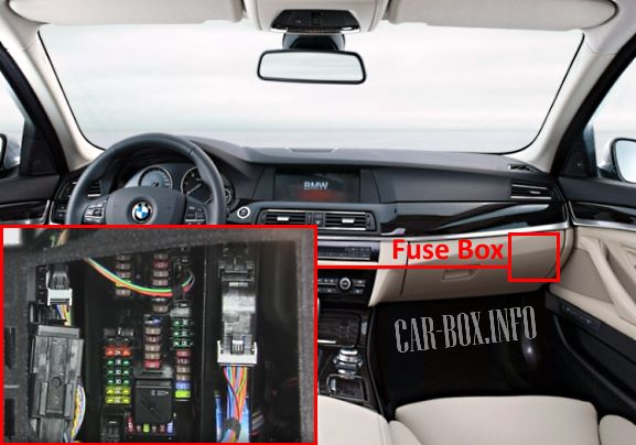
The mounting block is located in the glove compartment behind the protective cover.
General view of the BMW F10 / F11 / F07 interior fuse box.
| Diagram | ||
|---|---|---|

|
||
| No. | Decryption | A |
| 1 | Footwell control unit | 10 |
| 2 | Dynamic Stability Control (DSC) | 5 |
| Door control unit | ||
| 3 | Central Management Gateway | 5 |
| Diagnostic connector | ||
| 4 | Control unit (depending on configuration) | 5 |
| 5 | Reserve | — |
| 6 | Reserve | — |
| 7 | Junction box | 30 |
| 8 | 30 | |
| 9 | 30 | |
| 10 | instrument cluster | 10 |
| 11 | Heating and air conditioning control unit | 7.5 |
| 12 | Glove compartment illumination | 5 |
| 13 | Steering column switches | 5 |
| Driver assistance system | ||
| 14 | Junction box | 15 |
| 15 | 20 | |
| 16 | Footwell control module | 40 |
| 17 | 30 | |
| 18 | 30 | |
| 19 | trailer control module | 20 |
| 20 | Reserve | — |
| 21 | Reserve | — |
| 22 | Pressure control valve | 30 |
| Fuel metering solenoid | ||
| Camshaft sensor | ||
| Supercharger pressure regulator valve | ||
| Mass flow meter | ||
| Turbo control valve | ||
| Ramp pressure control valve | ||
| Fuel metering valve | ||
| Camshaft sensor | ||
| Rail pressure control valve | ||
| Compressor Bypass | ||
| 23 | Telematics | 5 |
| 24 | Steering column switches | 10 |
| 25 | Head-Head Display control unit | 5 |
| 26 | instrument cluster | 5 |
| 27 | Eject box | 5 |
| 28 | Video system (depending on configuration) | 5 |
| 29 | Rear control box | 5 |
| Touchbox control unit (depending on equipment) | ||
| 30 | Reserve | |
| 31 | Rear climate control unit | 5 |
| Heated rear seat switch | ||
| 32 | Driver seat adjustment switch | 7.5 |
| Door switch control unit | ||
| Passenger seat adjustment switch | ||
| Exterior rear view mirrors | ||
| hatch module | ||
| Rear lamp | ||
| 33 | Seat belt pretensioner control unit | 5 |
| Heating control unit | ||
| Tank vent valve | ||
| Fuel tank shut-off valve | ||
| Seat belt pretensioner control unit | ||
| Seat heating control unit | ||
| 34 | Chassis Integration Module | 5 |
| 35 | DDE main relay | 15 |
| 36 | headlight washer pump | 30 |
| 37 | Vertical dynamics control | 30 |
| 38 | Vehicle access control unit | 40 |
| 39 | Power steering control unit | 40 |
| 40 | Dynamic Stability Control (DSC) | 30 |
| 41 | Reserve | — |
| 42 | Electrohydraulic solenoids for motor mounting | 30 |
| EGR cooling bypass valve | ||
| Oil quality and oil level sensors | ||
| Oxygen sensor behind and before the catalytic converter | ||
| Mass flow meter | ||
| Electro-hydraulic engine mount solenoids | ||
| EGR cooling bypass valve | ||
| Compressor Bypass | ||
| Damper control solenoid valve | ||
| 43 | Electromechanical power steering | 5 |
| Throttle position valve | ||
| 44 | Automatic air conditioner | 5 |
| Camera control unit | ||
| 45 | Vertical dynamics control | 5 |
| Power steering control unit | ||
| 46 | Radiator shutter control unit | 5 |
| Cruise control | ||
| 47 | EGR coolant pump | 20 |
| Exhaust gas recirculation coolant pump | ||
| 48 | Electrochromic rear view mirror | 5 |
| Engine crankcase heater | ||
| 49 | Reserve | |
| 50 | Reserve | — |
| 51 | Wiper module | 30 |
| 52 | driver's seat control unit | 30 |
| Driver seat adjustment switch | ||
| 53 | Passenger seat control unit | 30 |
| Passenger seat adjustment switch | ||
| 54 | Front and rear 12V sockets, cigarette lighter fuse | 20 |
| 55 | Rear wiper | 20 |
| 56 | Vehicle access control unit | 5 |
| 57 | Spare | — |
| 58 | Noise filter | 5 |
| Sunroof module | ||
| 59 | intercooler pump | 10 |
| 60 | Parking brake switch | 5 |
| 61 | Sunroof (subject to availability) | 20 |
| 62 | Horn (beep) | 15 |
| 63 | Automatic transmission | 10 |
| 64 | selector switch | 7.5 |
| 65 | Additional socket 12V | 15/20 |
| Auxiliary heating system | ||
| 66 | Sunroof (if equipped) | 7.5 |
| Door switch control unit | ||
| Exterior mirror | ||
| 67 | Driver seat adjustment switch | 10 |
| Passenger seat adjustment switch | ||
| Valve block, lumbar support | ||
| 68 | Cooling Fan | 40 |
| 69 | Dynamic Stability Control (DSC) | 50 |
| 70 | Cooling fan shutdown relay | 60 |
| 71 | Fuel filter heater | 50 |
| R1 | Terminal 30 relay | |
|
||
| R1 | cooling fan cut-out relay | |
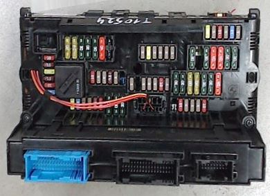
In the luggage compartment
There are three fuse mounting blocks and individual relays in the luggage compartment.
Fuse box
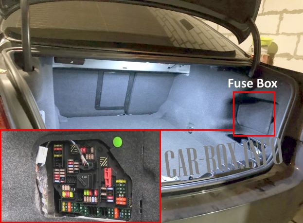
The main unit and auxiliary panel are located behind the trim on the right side.
| Assigmenent of fuses in the main luggage compartment box BMW F10 / F11 / F07 | ||
|---|---|---|
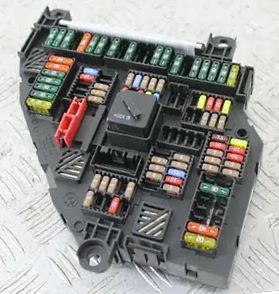
Photo is an example. |
||
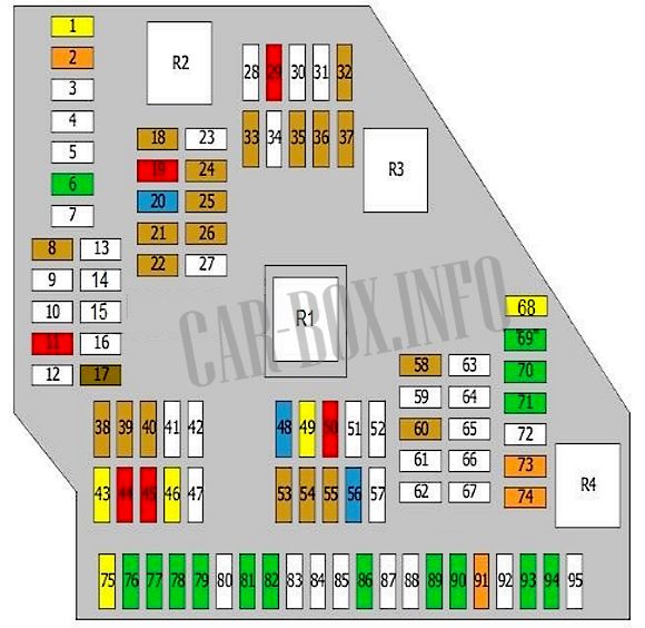
Diagram. |
||
| No. | Decryption | A |
| 1 | trailer control unit | 20 |
| 2 | Footwell control unit | 40 |
| 3 | Reserve | — |
| 4 | Reserve | — |
| 5 | Reserve | — |
| 6 | hi-fi amplifier | 30 |
| Headset connection module | ||
| 7 | Reserve | — |
| 8 | Charging management | 5 |
| Dynamic Stability Control (DSC) | ||
| 9 | Reserve | — |
| 10 | Reserve | — |
| 11 | automatic door | 10 |
| 12 | Reserve | — |
| 13 | Reserve | — |
| 14 | Reserve | — |
| 15 | Reserve | — |
| 16 | Reserve | — |
| 17 | Rear information display | 7.5 |
| 18 | Telematics | 5 |
| USB | ||
| 19 | Information display | 10 |
| Rear infotainment control unit | ||
| 20 | Headset connection module | 15 |
| Audio system | ||
| 21 | hi-fi amplifier | 5 |
| DVD | ||
| 22 | Cooling Fan | 5 |
| video system | ||
| Infotainment control unit | ||
| 23 | Reserve | — |
| 24 | Camera control unit | 5 |
| 25 | Night vision control unit | 5 |
| 26 | video system | 5 |
| 27 | Reserve | — |
| 28 | Reserve | — |
| 29 | Flap control solenoid | 10 |
| 30 | Reserve | — |
| 31 | Reserve | — |
| 32 | Lane Detection Warning | 5 |
| 33 | Additional heater | 5 |
| Folding roof control unit | ||
| Additional heater | ||
| Right high beam headlight | ||
| 34 | Reserve | — |
| 35 | Rear axle camber sensor | 5 |
| Assistance with parking | ||
| Servotronic (if equipped) | ||
| 36 | Electric changeover valve, exhaust flap | 5 |
| 37 | DC-DC Converter | 5 |
| Convertible roof control unit (if equipped) | ||
| 38 | Cooling fan shutdown relay | 5 |
| 39 | Transfer box (if equipped) | 5 |
| 40 | Fuel Tank Leak Diagnosis | 5 |
| Tire pressure monitoring (if equipped) | ||
| 41 | Reserve | — |
| 42 | Reserve | — |
| 43 | Auxiliary heating system (if equipped) | 20 |
| 44 | automatic door | 10 |
| 45 | 10 | |
| 46 | End connector | 20 |
| 47 | Reserve | — |
| 48 | Additional socket 12V | 15/20 |
| 49 | Folding roof control unit (if available) | 20 |
| Trailer towing module | ||
| 50 | automatic door | 10 |
| 51 | Reserve | — |
| 52 | Reserve | — |
| 53 | Ride height control | 5 |
| 54 | Trunk lid remote control | 5 |
| tailgate switch | ||
| 55 | trunk light | 5 |
| 56 | Rear door / trunk lock | 15 |
| 57 | Reserve | — |
| 58 | Parking brake control unit | 5 |
| 59 | Reserve | — |
| 60 | Signaling | 5 |
| emergency system | ||
| Vacuum leak detection | ||
| 61 | Reserve | — |
| 62 | Reserve | — |
| 63 | Reserve | — |
| 64 | Reserve | — |
| 65 | Reserve | — |
| 66 | Reserve | — |
| 67 | Reserve | — |
| 68 | heater fan | 20 |
| 69 | transfer box (if equipped) | 30 |
| 70 | Parking brake control unit | 30 |
| 71 | 30 | |
| 72 | Reserve | — |
| 73 | Compressor clutch relay | 40 |
| Soft top | ||
| 74 | Trunk lid remote control | 40 |
| 75 | Fuel pump fuse | 20 |
| 76 | Hi-Fi amplifier (if any) | 30 |
| 77 | DC-DC Converter | 30 |
| 79 | Control unit for heated rear seats | 30 |
| 80 | Reserve | — |
| 81 | Driver seat heating control unit | 30 |
| 82 | Passenger seat heating control unit | 30 |
| 83 | Reserve | — |
| 84 | Reserve | — |
| 85 | Reserve | — |
| 86 | Additional heater | 30 |
| 87 | Reserve | — |
| 88 | Reserve | — |
| 89 | Seat belt pretensioner control unit (if equipped) | 30 |
| 90 | 30 | |
| 91 | hi-fi amplifier | 40 |
| 92 | Reserve | — |
| 93 | Additional heater | 30 |
| 94 | Rear window heating | 30 |
| 95 | Reserve | — |
| R1 | Terminal 30 relay | |
| R2 | Terminal 30 relay | |
| R3 | Terminal 15 relay | |
| R4 | Heated rear window relay | |
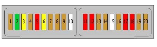
| Additional block №2 | ||
|
||
| No. | Purpose | A |
| 1 | Additional battery control unit | 5 |
| 2 | Reserve | |
| 3 | Additional battery control unit | 20 |
| 4 | Sound control unit | 5/2 |
| 5 | Charging connector | 10 |
| 6 | Sound control unit | 20 |
| 7 | Reserve | 5 |
| 8 | Reserve | 5 |
| 9 | Additional battery control unit | 5 |
| 10 | Reserve | - |
| 11 | Charging connector | 10 |
| 12 | 10 | |
| 13 | Reserve | 5 |
| 14 | Switches | 5 |
| 15 | Reserve | — |
| 16 | Additional battery control unit | 5 |
| 17 | Reserve | 10 |
| 18 | Additional battery control unit | 10 |
| 19 | 5 | |
| 20 | 5 | |
Relays
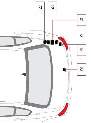
Description of the relay modules.
R1 - emergency alarms
R2 - rear electric windows
R3 - disconnection
R4 - rear electric windows
R5 - compressor clutch
F1 - 100.0 A - fuse box No. 2 in the luggage compartment
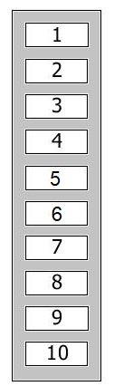
Power fusible links
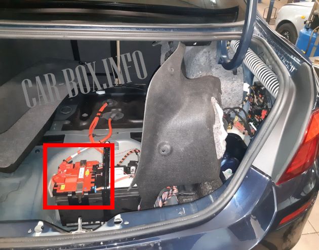
The battery is located under the trunk floor trim. On its plus terminal there is a board of high-power fusible links.
| Diagram | ||
|---|---|---|
|
||
| No. | Purpose | A |
| 1 | Cooling fan shutdown relay | 100 |
| 2 | DDE main relay | 100 |
| 3 | Electromechanical power steering | 125/100 |
| Trip relay | ||
| Fuse box No. 2 in the luggage compartment | ||
| 4 | Reserve | - |
| 5 | Reserve | - |
| 6 | hi-fi amplifier | 50 |
| 7 | Rear axle camber sensor | 60 |
| 8 | Fuse box No. 1 in the luggage compartment | 100 |
| 9 | Junction box | 250 |
| 10 | Fuse box No. 1 in the luggage compartment | 150/100 |
| Electromechanical power steering | ||
