Most of the electrical power circuits of the American sedan, station wagon and hatchback are protected by fuses. Powerful current consumers are connected via relays. Protective elements are installed in mounting blocks, which are located under the hood and in the passenger compartment.

The information on the diagrams is relevant for the Chevrolet Lacetti (J200) 1st generation 2004, 2005, 2006, 2007, 2008, 2009, 2010, 2011, 2012, 2013 models.
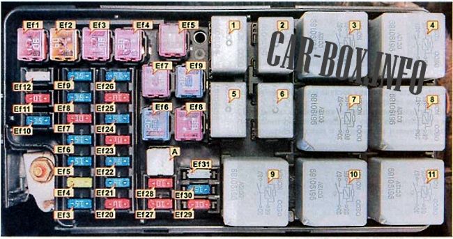
On the covers of the mounting boxes, the fuse layout, current rate and symbols of the protected circuits are marked.
In the engine compartment
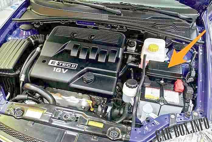
The fuse box is located on the left side of the engine compartment between the reservoir and the battery. To access it, you must remove the protective cover.
| Diagram | |
|---|---|
|
|
| Relays | |
| No. | Descripion |
| 1 | Illumination of devices and controls / 96190187 |
| 2 | Sound signal / 96190187 |
| 3 | Main relay / ignition relay / 96190189 |
| 4 | Block headlights / 96190189 |
| 5 | Fog lights / 96190187 |
| 6 | Air conditioning compressor clutch / 96190187 |
| 7 | Fuel pump relay / Fuel pump, ignition coils / 96190189 |
| 8 | Power windows / 96190189 |
| 9 | Engine cooling fan (low speed) / 96190189 |
| 10 | Heated rear window / 96190189 |
| 11 | Engine cooling fan (high speed) / 96190189 |
| Fuses and the circuits they protect | ||
| No. | Amps | Description |
| BUT | - | Tweezers for removing fuses |
| Ef1 | 30 | Hazard alarm, anti-theft control unit, diagnostic socket, rear fog lights, clock, air conditioning, air conditioning switch, audio system, immobilizer, automatic transmission control unit |
| Ef2 | 60 | ABS control unit, ABS executive unit |
| Ef3 | 30 | Air conditioner fan |
| Ef4 | 30 | Power windows, power mirrors, starter |
| Ef5 | 30 | Fuel pump activation relay, electronic engine control unit, exhaust gas recirculation valve, ignition system, fuel pump, fuel vapor recovery system purge valve. engine cooling fan |
| Ef6 | 20 | Engine cooling fan (low speed) |
| Ef7 | 30 | Heated rear window |
| Ef8 | 30 | Engine cooling fan (high speed) |
| Ef9 | 20 | Power windows (except driver's door) |
| Efl0 | 15 | Fuel pump ON relay, ECM, EGR valve, ignition system |
| Efl1 | 10 | Main relay power supply circuit |
| Efl2 | 25 | Headlights, illumination of devices and controls |
| Efl3 | 15 | Brake signal |
| Efl4 | 20 | Power windows (driver's door) |
| Efl5 | 15 | High beam headlights |
| Ef16 | 15 | Sound signal |
| Ef17 | 10 | Air Conditioning Compressor A / C |
| Ef18 | 15 | Fuel pump power supply circuit |
| Ef19 | 15 | Instrument cluster, horn switch, electric folding mirrors, individual lighting, interior lighting, trunk lighting, dates and to the open tailgate |
| Ef20 | 10 | Low beam (left headlight) |
| Ef21 | 15 | EVAP canister purge valve, heated oxygen sensor, engine cooling fan |
| Ef22 | 15 | Nozzles, waste can recirculation system |
| Ef23 | 10 | License plate lights, hazard warning lights, rear light, headlamp unit (left side) |
| Ef24 | 15 | Fog lights |
| Ef25 | 10 | Electric drive and heated rear-view mirrors |
| Ef26 | 15 | Central locking system |
| Ef27 | 10 | Low beam (right headlight) |
| Ef28 | 10 | License plate lights, hazard warning lights, tail light, headlamp unit (right side) |
| Ef29 | 10 | Spare |
| Ef30 | 15 | Spare |
| Ef31 | 10 | Spare |
In the passenger compartment
Fuse box
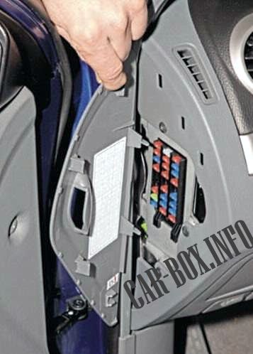
Located on the left side at the end of the dashboard. Access is by opening the left front door and removing the fuse panel cover.
| Diagram | |
|---|---|
|
|
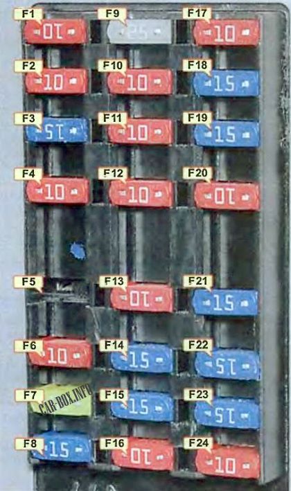
| No. | Amps / Description |
| F1 | 10A AIRBAG - Electronic airbag control unit |
| F2 | 10A ECM - Electronic engine control unit, electronic control unit for automatic transmission *, generator, vehicle speed sensor |
| F3 | 15A TURN SIGNAL - Hazard switch, direction indicators |
| F4 | 10A CLUSTER - Instrument panel, electronic unit for automatic switching on of low beam headlights *, buzzer, brake signal switch, electronic steering gear control unit with variable effort *, air conditioner switch * |
| F5 | Reserve |
| F6 | 10А ENG FUSE - Relay for turning on the air conditioner compressor, relay for turning on the heated rear window, relay for turning on electric windows, relay for turning on headlights |
| F7 | 20A HVAC - Relay for turning on the electric air conditioner fan, air conditioner switch, climate control system * |
| F8 | 15A SUNROOF - Electric mirrors switch, electric folding mirrors *, electric sunroof * |
| F9 | 25А WIPER - Wiper gear motor, wiper mode switch |
| F10 | 10А HANDS FREE - Speakerphone |
| F11 | 10A ABS - ABS control unit. ABS executive unit |
| F12 | 10А IMMOBILIZER - Immobilizer, electronic anti-theft alarm control unit, rain sensor |
| F13 | 10A Automatic transmission control unit * |
| F14 | 15A HAZARD - Alarm switch |
| F15 | 15A ANTI-THEFT - Electronic anti-theft alarm control unit |
| F16 | 10A DIAGNOSIS - Diagnostic connector |
| F17 | 10A AUDIO / CLOCK - Audio system, clock |
| F18 | 15А EXTRA JACK - Additional socket |
| F19 | 15A CIGAR LIGHTER - Cigarette lighter fuse |
| F20 | 10A BACK-UP - Reversing light switch, automatic transmission mode selector * |
| F21 | 15А REAR FOG - Relay for turning on rear fog lamps, relay for lighting devices and controls, side lighting |
| F22 | 15A ATC / CLOCK - Clock, climate control system *, air conditioner switch * |
| F23 | 15A AUDIO - Audio system |
| F24 | 10А IMMOBILIZER - Immobilizer |
Additional relay modules

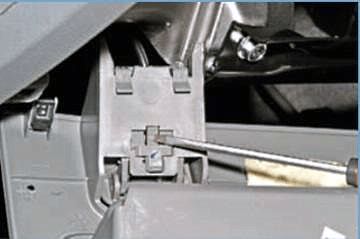
To get to them you need to open the coin box and unscrew two screws with a screwdriver
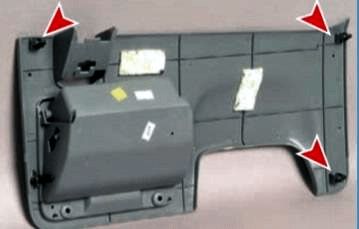
Further, overcoming the resistance of the three clips, remove the lower trim from the instrument panel with the clips
Then, pressing the latch. We release the handle of the drive of the hood lock and remove the lower lining. The relays are located on a bracket fixed to the dashboard frame.

We reach the modules by hand.
Relay circuit under the dashboard
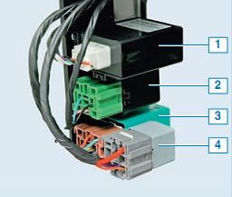
Purpose of components : 1 - battery protection system control unit; 2 - interrupter of direction indicators; 3 - relay for turning on the fog light in the rear lights; 4 - starter blocking relay (for cars with an automatic transmission). Depending on the vehicle configuration, (BLOWER RELAY) - air conditioner fan relay, (DRL RELAY) - forced headlight system relay are also installed there.
