Voyager and Caravan are a series of minivans produced by the American corporation Chrysler. European sales started in 1984. In this material, we will analyze in detail the fuse diagrams for the Dodge Caravan / Chrysler Voyager (3rd generation) 1995, 1996, 1997, 1998, 1999, 2000, 2001 of release.
Here you will find the locations and photos of the fuse blocks. Separately, we note the elements responsible for the cigarette lighter and fuel pump.
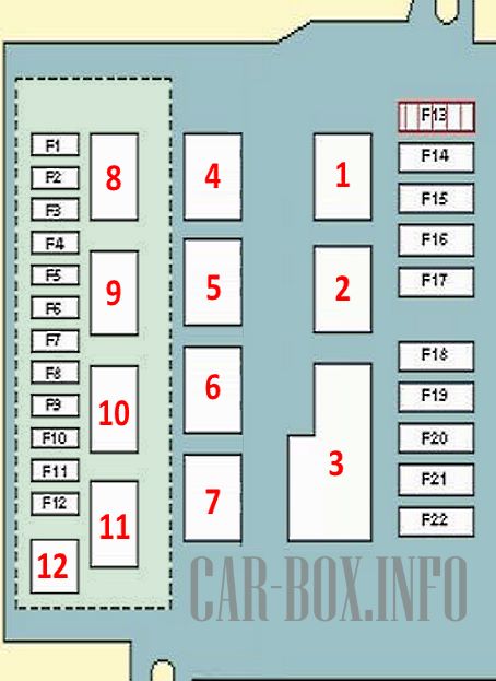
In the passenger compartment
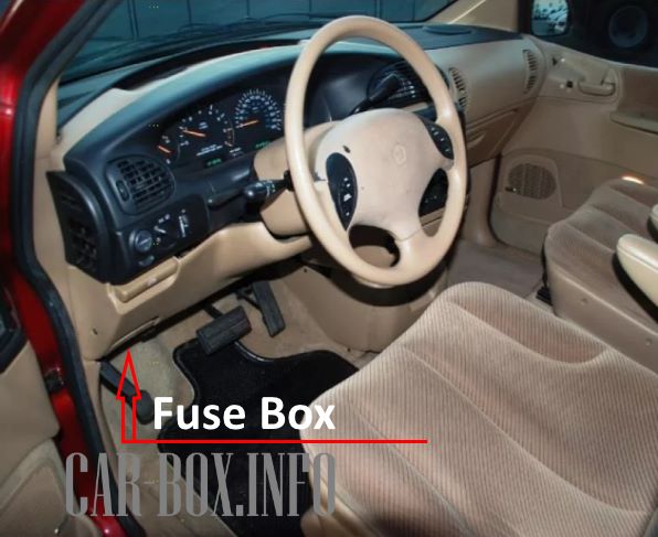
Located under the dashboard.
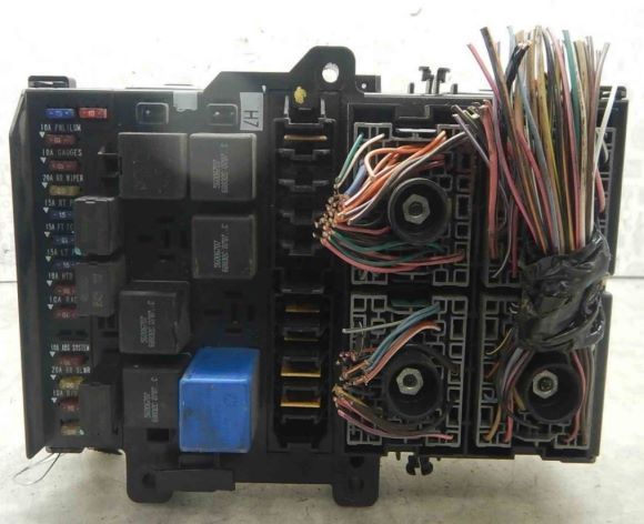
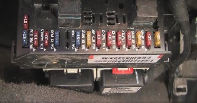
General view of the block.
Access example.
| Cabin Fuse Block Diagram | ||
|---|---|---|
|
||
| No. | Description | A |
| F1 | Lamp(s) for illumination of the instrument cluster, right position lamps, front | 10 |
| F2 | instrument cluster | 10 |
| F3 | Parking lights, right | 15 |
| F4 | Fog lights | 15 |
| F5 | License plate lamp, left position lamps, front | 15 |
| F6 | Instrument cluster indicators, air conditioning systems | 20 |
| F7 | Power mirrors | 10 |
| F8 | Audio system | 10 |
| F9 | Reserve | 15 |
| F10 | Limit switch (position sensor) clutch pedal | 10 |
| F11 | A/C heater fan motor, rear | 20 |
| F12 | ABS System, Rear Defroster Relay, Seat Heater Switch (Driver) | 10 |
| F13 | Fuel Heater Relay/Fuel Pump Relay | 9 |
| F14 | Reserve | 9 |
| F15 | Central locking relay (driver's door) | 9 |
| F16 | Reserve | 9 |
| F17 | Reserve | 9 |
| F18 | Reserve | 9 |
| F19 | Windshield Washer Pump - Front and Rear | 9 |
| F20 | Power Window Switch (Driver's Door), Power Window Switch (Passenger's Door) | 9 |
| F21 | Power Window Switch (Driver's Door) | 9 |
| F22 | Reserve | 9 |
| Relay modules | ||
| 1 | Central locking - unlock | |
| 2 | Central locking - blocking | |
| 3 | Hazard/Turn Signal Relay | |
| 4 | Central locking (driver's door) - unlocking | |
| 5 | Windshield washer pump | |
| 6 | Mirror folding system - folding | |
| 7 | Mirror folding system - unfolding | |
| 8 | Rear window heater | |
| 9 | Audio system | |
| 10 | Fog lights | |
| 11 | Interior lamps | |
| 12 | Multifunction control box | |
In the engine compartment
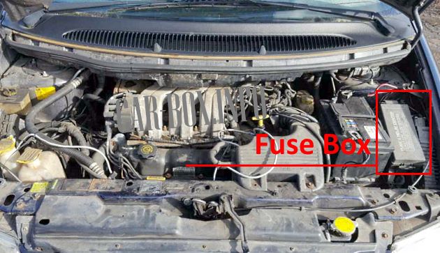
Located near the battery. To access, you need to remove the protective cover.
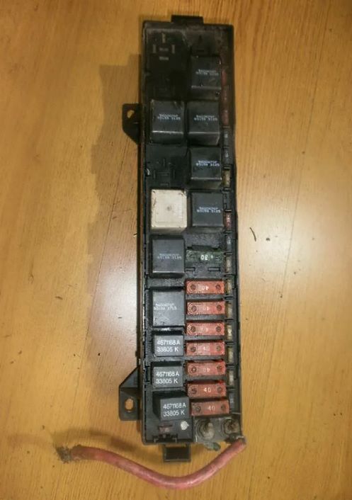
Execution example.
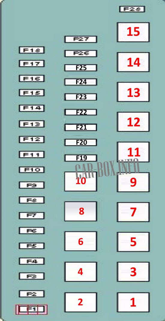
| Diagram | ||
|---|---|---|
|
||
| No. | Description | A |
| F1 | Airbags | 10 |
| F2 | 10 | |
| F3 | Reserve | |
| F4 | High beam lamp (left) | 10 |
| F5 | High beam lamp (right) | 10 |
| F6 | Low beam lamp (left) | 20 |
| F7 | Low beam lamp (right) | 15 |
| F8 | Accessory Connector, Dodge Caravan / Chrysler Voyager Cigarette Lighter Fuse | 20 |
| F9 | Sound signal | 20 |
| F10 | Daytime Running Lights, Turn Signals/Hazards, Parking Lamp Relays | 20 |
| F11 | Air conditioning system | 15 |
| F12 | Anti-Lock Braking System (ABS) | 25 |
| F13 | Stop lights | 20 |
| F14 | Reserve | |
| F15 | Automatic transmission | 20 |
| F16 | fuel pump fuse Dodge Caravan / Chrysler Voyager | 20 |
| F17 | Engine management | 20 |
| F18 | Power door mirrors, interior lamps | 15 |
| F19 | windshield wiper | 30 |
| F20 | Cooling Fan Motor Relay 3 - Diesel | 40 |
| F21 | Heater fan motor relay | 40 |
| F22 | F3/F4/F5 circuit protection - cabin fuse box | 40 |
| F23 | Ignition lock, starter relay | 40 |
| F24 |
|
40 |
| F25 | Anti-lock braking system (ABS) | 40 |
| F26 | Circuit protection F15 - in the cabin fuse box | 40 |
| F27 | Rear defroster relay | 40 |
| F28 | Audio system, ignition lock, instrument cluster | 10 |
| Relay modules | ||
| 1 | Reserve | |
| 2 | cigarette lighter relay | |
| 3 | Sound signal | |
| 4 | Windshield wiper motor | |
| 5 | A/C Compressor Clutch | |
| 6 | Windshield wiper motor | |
| 7 | Reserve | |
| 8 | high beam headlights | |
| 9 | Heater fan motor relay | |
| 10 | dipped headlights | |
| 11 | Starter | |
| 12 | parking lights | |
| 13 | transmission control system | |
| 14 | Fuel Heater (Diesel) or Fuel Pump Relay |
|
| 15 | Engine management system | |
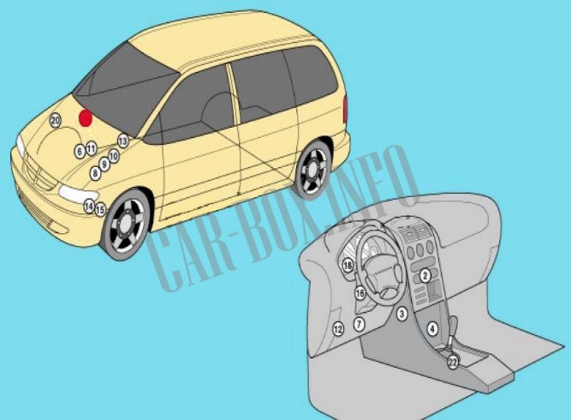
General arrangement
Location of the electronic components.
|
|
| No. | Component |
| 1 | Air conditioning refrigerant pressure sensor |
| 2 | A/C/Heater Fan Motor Control Module -in Control Panel |
| air conditioning/heater | |
| 3 | Air temperature sensor behind the air conditioner evaporator |
| 4 | SRS electronic control module |
| 6 | Accumulator battery |
| 7 | Diagnostic connector (DLC) |
| 8 | Cooling fan motor relay 1 |
| 9 | Cooling Fan Motor Relay 2 - Diesel |
| 10 | Cooling Fan Relay - Diesel |
| 11 | Fuse box / relay in the engine compartment |
| 12 | Fuse box and relay in the cabin |
| 13 | Heater blower motor resistor |
| 14 | Horn 1 - behind the front bumper |
| 15 | Horn 2 - behind the front bumper |
| 16 | Electronic immobilizer control module |
| 18 | keylessentry system control unit |
| 20 | Electronic transmission control module |
| 22 | Automatic transmission selector position sensor |
