Most of the power supply circuits of the Japanese crossover electrical equipment are protected by fuses. Headlights, fan motors, fuel pump and other powerful current consumers are connected via relays. Protective elements are installed in mounting blocks located in the engine compartment and passenger compartment.

Information on the diagrams is intended for cars Honda CR-V 3rd generation (RE) 2006, 2007, 2008, 2009, 2010, 2011, 2012 model year.
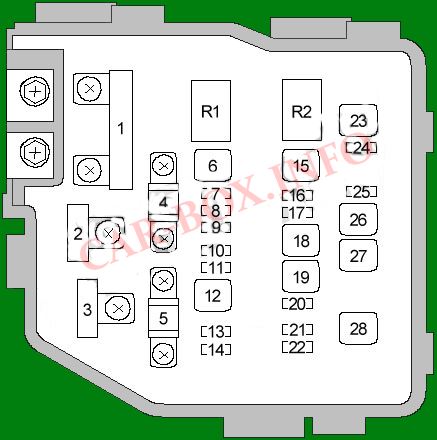
In the passenger compartment
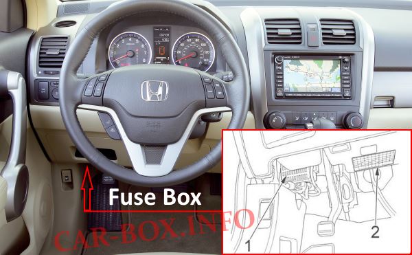
The fuse box (1) is located on the driver's side, at the bottom of the dashboard. The decoding plate (2) is located under the steering column.
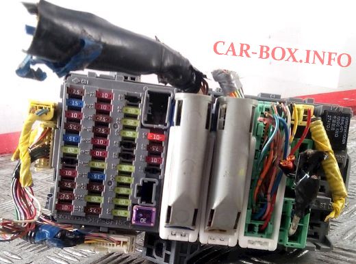
Photo is an example.
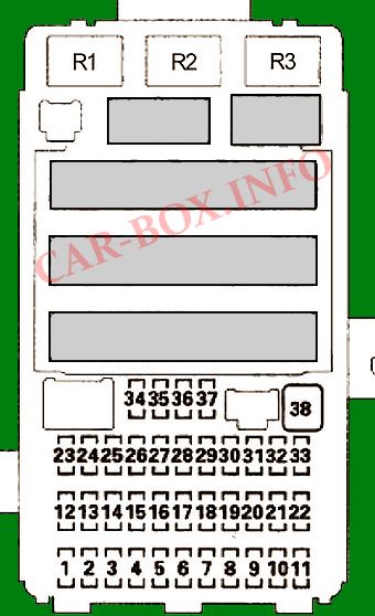
| Diagram | ||
|---|---|---|
|
||
| No. | A | Description |
| 1 | 7.5 | Rain / auto light switch, headlamp leveling motor, headlight leveling switch, main power window switch, sunroof motor / control unit |
| 2 | 15 | ECM / PCM (IG1), immobilizer remote control unit |
| Fuel module / petrol pump (via main relay PGM-FI 2) | ||
| 3 | 10 | Alternator, brake pedal position sensor (with cruise control), CMP sensor B, ELD unit, EVAP tank purge valve, MAF sensor, reverse lock solenoid (MCP), secondary HO2S sensor |
| 4 | 7.5 | ABS modulator control unit, VSA modulator control unit, EPS control unit, vehicle yaw rate and lateral acceleration sensor (with VSA) |
| 5 | 15 | Electric seat heater |
| 6 | 20 | Front fog lights |
| 7 * 1 | 10 | Daytime running light relay |
| 8 | 10 | Automatic headlight deflection control unit, rear wiper motor (via rear wiper motor relay) |
| 9 | 7.5 | E-pretensioner unit, OPDS unit, SRS unit |
| 10 | 7.5 | Reverse gear shift sensor (MCP), electric compass unit, instrument control module, MICU (IG1), parking and reverse gear sensor, shift lock solenoid (AT) |
| 11 | 10 | SRS unit |
| 12 | 10 | Right headlight (high beam) |
| 13 | 10 | Left headlight (high beam) |
| 14 | 7.5 | AFS / CMBS switch illumination, audio unit illumination, automatic transmission gear position indicator panel illumination, climate control unit illumination, glove box illumination, hazard warning switch illumination, HVAC control unit illumination, headlight direction switch illumination, microphone (with navigation), parking sensor illumination and reverse, seat heater switch lights, sunroof switch lights, sun visor switch lights, electric mirror switch lights, steering wheel switch lights, VSA OFF switch lights |
| 15 | 7.5 | Front side lights, license plate lights, rear lights |
| 16 | 10 * 3 15 * 4 | Right headlight (low beam), headlight washer control unit |
| 17 | 10 * 3 15 * 4 | Left headlight (low beam) |
| 18 | 20 | MICU (+ IN H / L HI) |
| 19 | 15 | MICU (+ IN SMALL) |
| 20 | 7.5 | MICU (+ IN RR FOG) |
| 21 | 20 * 3 30 * 4 | MICU (+ BH / L LO) |
| 22 | 7.5 | Adaptive cruise control (ACC) relay, adaptive cruise control (ACC) unit, automatic headlight range control unit, millimeter wave radar unit |
| 23 | Not used | |
| 24 | 20 | Motor / sunroof control unit, electric motor / sun visor control unit |
| 25 | 20 | Super interlocking relay (KE model) |
| MICU (+ IN DR LOCK) | ||
| 26 | 20 | Power window main switch |
| 27 | Not used | |
| 28 | 15 * 5 20 * 6 |
Luggage Compartment Accessory Power Socket Relay |
| 29 | 15 * 5 20 * 6 | Front Accessory Power Socket Relay / Cigarette Lighter Fuse Honda CR-V |
| 30 | 20 | Front passenger door power window motor, front passenger door power window switch * 2 |
| 31 | 15 * 5 20 * 6 | Accessory Power Console Socket Relay |
| 32 | 20 | Rear right power window motor, rear right power window switch * 2 |
| 33 | 20 | Rear left door power window motor, rear left door power window switch 2 |
| 34 | 7.5 | Accessory power socket relay, audio unit, Hands free phone control unit |
| 35 | 7.5 | Key lock solenoid, MICU |
| MICU | ||
| 36 | 10 | Climate control unit, daytime running light relay, HVAC control unit, electric mirrors actuators, recirculation control motor, engine compartment relay / fuse box (air conditioning clutch relay, air conditioning condenser fan relay, heater motor relay, radiator fan relay, rear heater relay glass), cooling fan control relay and radiator fan relay (via the air conditioner diode) |
| 37 '1 | 7.5 | MICU (DAYLT) |
| 38 | 30 | MICU (IG1 WIPER) |
| R1 | Window lifters | |
| R2 | Fuel pump relay | |
| R3 | Starter relay | |
| * 1 Model KS * 2 With driver's window function AUTO UP / AUTO DOWN * 3 Without HID * 4 With HID * 5 Except for KG, KS and KE models * 6 KG, KS and KE models | ||
In the engine compartment
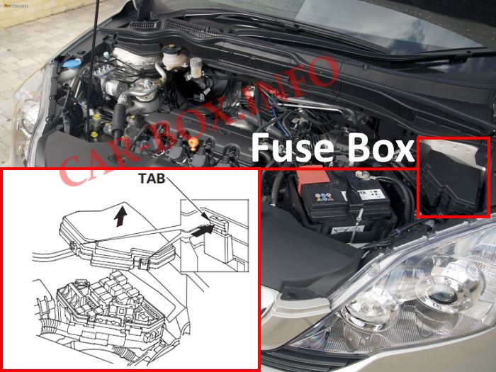
The fuse block is located on the left side of the engine compartment, near the battery.

Photo is an example.
| Diagram (Diesel Engines) | ||
|---|---|---|
|
||
| No. | Appointment | A |
| 1 | Accumulator battery | 100 |
| VSA pump | 40 | |
| 2 | Egnition lock | 50 |
| Fuses (salon): 18, 21 | 50 | |
| 3 | Seat belt pre-tensioning system | 30 |
| 4 | Fuses (salon): 5, 6, 7, 27, 28, 29, 31 | 80 |
| 5 | Glow plug control unit | 70 |
| 6 | Fuses (interior): 24, 25, 26, 30, power window relay | 40 |
| 7 | A / C Compressor Clutch Relay | 7.5 |
| 8 | Glow Plug Control Module, Oil Level Gauge, Reverse Lock Solenoid Valve, PGM-FI Main Relay 2, Radiator Fan Relay, ECM (via ISV Control Relay), PGM-FI Main Relay 2, Fuse (Engine Compartment): # 10 , ISV control relay | 15 |
| 9 | Intake plate valve (via ISV control relay) | 15 |
| 10 | A / C Condenser Fan Relay, Cooling Fan Control Relay, EGR Solenoid, Fuel Heater Relay, Glow Plug Control Module, Reverse Lock Solenoid Valve, SCV Solenoid, Turbocharger Gain Control Solenoid, EGR Cooler Bypass Solenoid | 7.5 |
| 11 | - | - |
| 12 | Heater relay | 40 |
| 13 | VSA control unit | 20 |
| 14 | Audio system, subwoofer | 15 |
| 15 | Heated rear window relay | 30 |
| 16 | Body electronics unit (MICU), immobilizer-remote control unit, instrument cluster, hands-free system, audio system, diagnostic connector (DLC), navigation (AVN), ultrasonic sensor (with ultrasound), burglar alarm siren (with ultrasound) ) | 10 |
| 17 | Interior lighting, rain / auto light switch, luggage compartment lighting, ceiling lamp, local lamp, ignition switch lighting, vanity mirror lamps | 7.5 |
| 18 | Fuel heater relay, fuse (passenger compartment): No. 20 | 30 |
| 19 | Cooling Fan Relay, A / C Fan Relay | 30 |
| 20 | Engine control unit - ECM (FHTR MON) | 7.5 |
| 21 | Brake pedal position sensor (brake light), horn relay, body electronics unit (MICU), adaptive cruise control (ACC), VSA control unit | 15 |
| 22 | Body Electronics Unit (MICU) | 15 |
| 23 | Air conditioner fan relay | 30 |
| 24 | ECM (via PGM-FI Relay 1), Rail Pressure Control Valve (via PGM-FI Relay 1), PGM-FI Main Relay 1, PGM-FI Main Relay 2 | 20 |
| 25 | - | - |
| 26 | Power seat control unit | 20 |
| 27 | Driver's seat adjustment switch (longitudinal travel), driver's lumbar support switch | 20 |
| 28 | Headlight washer control unit | 30 |
| Relay | ||
| R1 | A / C Compressor Clutch | |
| R2 | Fan | |
| Diagram (petrol engines) | ||
|---|---|---|
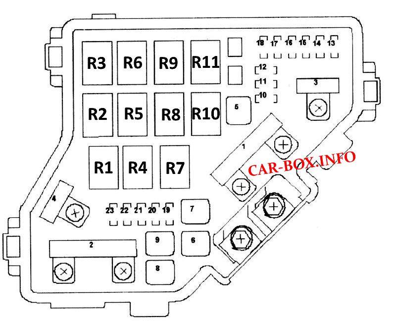
|
||
| No. | A | Decoding |
| 1 | 100 | Battery, power distribution |
| 70 | EPS control unit | |
| 2 | 50 | Egnition lock |
| 80 | Fuses # 5, # 6, # 7, # 27, # 28, # 29 and # 31 in the relay / fuse box under the dash | |
| 3 | 40 | ABS modulator control unit, VSA modulator control unit |
| 20 | ||
| 4 | 50 | Fuses # 18, # 19, # 20 and # 21 in the under-dash fuse / relay box (H / L) |
| 40 | Fuses # 24, # 25, # 26, # 30, # 32 and # 33 and the power window relays in the under-dash fuse / relay box (P / W) | |
| 5 | 30 | E-pretensioner unit |
| 6 | 20 | Air conditioner condenser fan drive |
| 7 | 20 | Cooling fan motor |
| 8 | 30 | Power window heater relay, rear window heater |
| 9 | 40 | Interior blower motor |
| 10 | 15 | MICU (+ IN HAZARD) |
| 11 | 15 | Repeat of the sensor of the ratio of air mass to fuel mass (A / F) |
| A / F sensor (via A / F sensor relay) | ||
| 12 | 15 | Adaptive Cruise Control (ACC) Relay / TSA Relay, Horn Relay (with Security System), MICU |
| 13 | 20 | Driver seat adjustment switch (tilt, rear up / down) |
| 14 | 20 | Driver's seat adjustment switch (sliding, front up / down), driver's lumbar support switch |
| 15 | 7.5 | Air conditioner condenser fan relay |
| Engine oil level sensor * 1 | ||
| 16 | 30 | E-pretensioner unit |
| 17 | 15 | Audio unit, woofer |
| 18 | 15 | Ignition coil relay |
| Ignition coils | ||
| 19 | 15 | ETCS Control Relay, PGM-FI Main Relay 1 (Fl MAIN) |
| SKR Sensor, CMP Sensor, ECM / PCM, Injectors, PGM-FI Main Relay 2 (FUEL PUMP) | ||
| 20 | 7.5 | A / C compressor clutch relay |
| 21 | 15 | ECM / PCM (via ETCS control relay) |
| 22 | 7.5 | Rain / auto light sensor, luggage compartment lighting, ceiling lamp, local lamp, ignition switch lighting, vanity mirror lamps |
| 23 | 10 | Alarm control siren, audio unit, Avn unit, data transfer connector (DLC), instrument control module, Hands free telephone control unit, remote control unit - immobilizer, ultrasonic sensor |
| R1 | Cooling fan | |
| R2 | Air conditioner fan | |
| R3 | Fan control | |
| R4 | Throttle body (ETCS) | |
| R5 | Heater | |
| R6 | Rear wiper | |
| R7 | Engine control unit (No. 1) | |
| R8 | Heated rear window | |
| R9 | Air-Fuel Ratio (A / F) Sensor | |
| R10 | A / C Compressor Clutch | |
| R11 | Ignition coils | |
| [] Vehicle with RHD * 1 Engine K24Z1 | ||
