This sedan, based on the Fit model, has gained great popularity in the Japanese market. It began production at the end of 2002 and became the 4th model in the SMALL MAX series, continuing the Fit, Mobilio and Mobilio Spike concepts. In this material, we will analyze in detail the fuse circuits of Honda Fit Aria (first generation; GD) 2002, 2003, 2004, 2005, 2006, 2007, 2008, 2009 2WD & 4WD.
Here you will find the locations and photos of the fuse boxes. Separately, we note the elements responsible for the cigarette lighter and fuel pump.
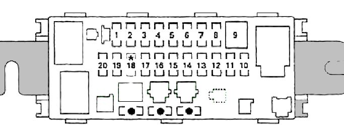
In the passenger compartment

Located on the driver's side, at the bottom of the dashboard, behind a plastic cover.
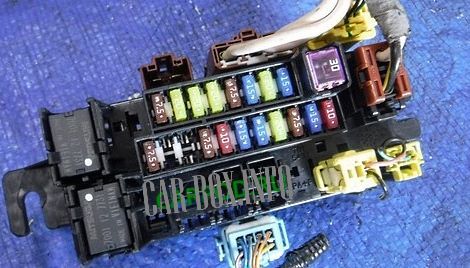
General view of the block.
| Diagram | ||
|---|---|---|
|
||
| No. | Description | A |
| 1 | Cooling system radiator relay, condenser fan relay, compressor electromagnetic clutch relay, heater fan motor relay, electric mirror drives, air conditioner switch, rear window defogger switch | 7.5 |
| 2 | Front passenger door power window | 20 |
| 3 | Power window regulator, rear right door | 20 |
| 4 | Electric power window rear left door | 20 |
| 5 | Ignition key lock control circuit (built into the instrument cluster), ignition key lock solenoid valve, radio | 7.5 |
| 6 | Cigarette lighter fuse Honda Fit Aria | 15 |
| 7 | Driver's door power window | 20 |
| 8 | Powertrain control unit, main injection system relay No. 1, main injection system relay No. 2, crankshaft position sensor, camshaft position sensor, idle speed control valve, injectors, immobilizer receiver (models from 03/2004 onwards) ) | 15 |
| 9 | Heated rear window | 30 |
| 10 | SRS electronic control unit | 10 |
| 11 | Powertrain control unit, fuel pump fuse, SRS electronic control unit | 15 |
| 12 | Pressure modulator and ABS control unit, supply voltage control unit (models up to 10/2005), electronic control unit for power steering (models up to 10/2005), selector lever lock solenoid valve (models up to 10/2005), combination devices (models up to 10/2005), central locking remote control unit (models from 10/2005), generator (models up to 10/2005), oxygen sensor (models from 10/2005), recovery system solenoid valve topple vapors (models from 10/2005) | 7.5 |
| 13 | Drive motor clean windshield glass, washer pump | 20 |
| 14 | Ignition coils (front row) | 15 |
| 15 | Ignition coils (rear row) | 15 |
| 16 | Direction indicator and hazard warning light control circuit (instrument cluster) | 10 |
| 17 |
|
7.5 |
| 18 | No | - |
| 19 | Rear window wiper motor | 10 |
| 20 | Reversing light relay | 7.5 |
| Relay | ||
|
||
| 1 | Power window relay | |
| 8 | Reversing light relay | |
| Rest: wiring harnesses, or not used | ||
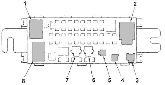
In the engine compartment
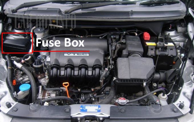
The location of the fuse box in the engine compartment of the car.
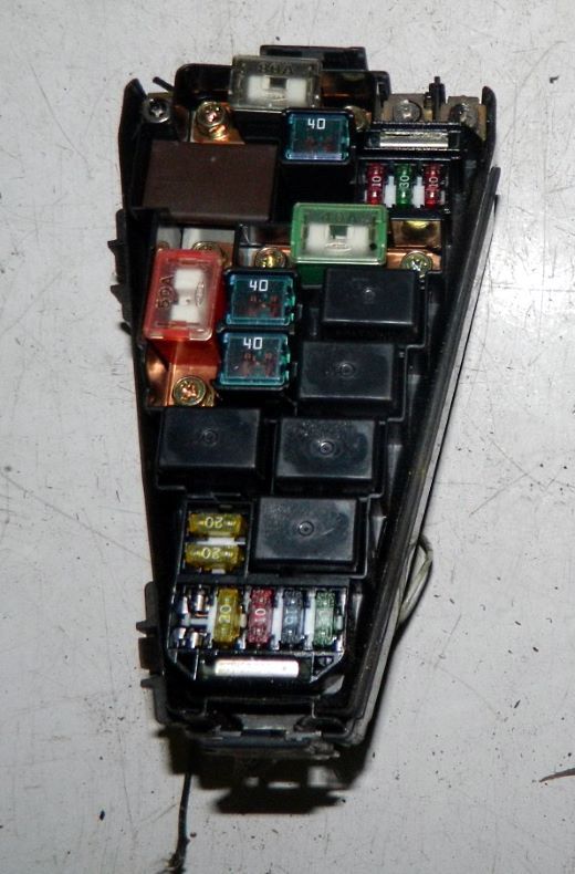
Photo is an example.
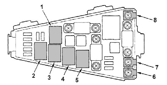
| Diagram | ||
|---|---|---|

|
||
| No. | Decoding of fuses | A |
| 1 | Accumulator battery | 80 |
| 2 | Power steering electronic control unit | 40 |
| 3 | Egnition lock | 50 |
| 4 | Pressure modulator and ABS control unit | 40 30 * |
| 5 | Heater blower motor | 40 |
| 6 | Fuses No. 2, No. 3, No. 4, No. 7, No. 8, No. 9 (fuse box in the passenger compartment) | 50 |
| 7 | Electric drives for door locks | 20 |
| 8 | Diagnostic socket, radio, instrument cluster, remote control for central locking, luggage compartment lamp, interior lamp, local illumination lamp, immobilizer receiver (models from 03/2004) | 10 |
| 9 | switch illumination, instrument cluster illumination, air conditioning and heating control panel illumination, radio cassette illumination, tail lights, license plate illumination, selector position indication panel illumination | 10 |
| 10 | Cooling fan motor | 20 |
| 11 |
|
20 |
| 12 |
|
20 |
| 13 |
|
20 |
| 14 | Direction indicator and hazard warning light control circuit (instrument cluster) | 10 |
| 15 | Pressure modulator and ABS control unit | 30 20 * |
| 16 |
|
10 |
| * - models of release from 10/2005 | ||
| Relay | ||
|
||
| 2 | Compressor electromagnetic clutch relay | |
| 3 | Condenser fan motor relay | |
| 1 | Headlight relay | |
| 5 | Cooling fan motor relay | |
| 4 | Horn relay | |
