Honda Fit for the domestic Japanese market (in the European market the car is called the Honda Jazz) has been produced since June 2001 and since that moment has not ceased to maintain a high level of sales and great popularity. This small car looks like a minivan with incredible sportiness. The model, targeting the American market, debuted at the Detroit Auto Show in January 2006. In this material, we will analyze in detail the fuse circuits (GD) of the first generation 2001, 2002, 2003, 2004, 2005, 2006, 2007 release.
Here you will find the locations and photos of the fuse boxes. Separately, we note the elements responsible for the cigarette lighter and fuel pump.
In the passenger compartment
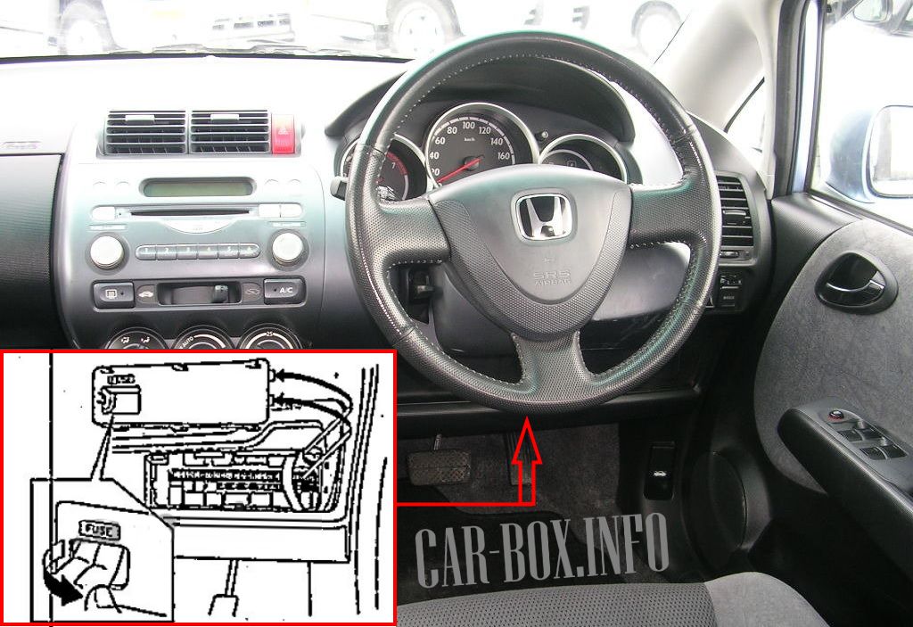
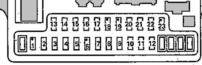
Fuse box located on the driver's side at the bottom of the dashboard.

General view of the block.
| Diagram | ||
|---|---|---|
|
||
| No. | Decoding | A |
| 1 | Empty | - |
| 2 | Driver's door power window | 20 |
| 3 | Driver's door lock electric drive, rear door lock electric drive | 20 |
| 4 | Power window regulator, rear right door | 20 |
| 5 | Turn signal and alarm circuit (instrument cluster), reversing light relay, reversing lights | 10 |
| 6 | No | - |
| 7 | Ignition coil (front) | 15 |
| 8 | Connector for additional equipment, cigarette lighter fuse jazz / fit | 15 |
| 9 | Front passenger position detection system unit, ignition coil (rear) | 15 |
| 10 | Windshield wiper motor, electric washer pump | 20 |
| 11 | Electronic control unit PGM-FI, fuel module (fuel pump fuse honda jazz / fit), electronic control unit SRS | 15 |
| 12 | Heated rear window | 20 |
| 13 | Power window regulator, rear left door | 20 |
| 14 | Front passenger door power window | 20 |
| 15 | SRS electronic control unit | 10 |
| 16 | Sunroof control unit, pressure modulator and ABS electronic flea control system, supply voltage monitoring system unit, EPS electronic control unit, e / m switch lock valve, instrument cluster, central locking remote control unit, generator, oxygen sensor, electropneumatic vapor recovery system valve fuel | 7.5 |
| 17 |
|
7.5 |
| 18 | Connector for additional equipment | - |
| 19 | No | - |
| 20 | Electronic control unit PGM-FI, the main relay of the injection system No. 1, the main one is the relay of the injection system No. 2, the crankshaft position sensor, the valve of the idle speed control system, the TDC sensor; injectors | 15 |
| 21 |
|
10 |
| 22 |
|
7.5 |
| 23 | No | - |
| Relay | ||
|
||
| 33 | Fog lamp relay | |
| 34 | Heater blower motor relay | |
| 32 | Main Relay # 1 PGM-FI | |
| 31 | Main Relay # 2 PGM-FI | |
| 18 | Power window relay | |
| 30 | Central locking / fuel system lockout (restart) relay | |
| 29 | Central locking / fuel system lockout (restart) relay | |
| 37 | Reversing light relay | |
| 28 | Starter | |
| 35 | Tail lamps | |
| Rest: either wiring harnesses or not used | ||
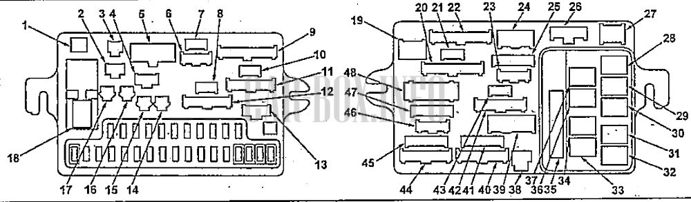
In the engine compartment
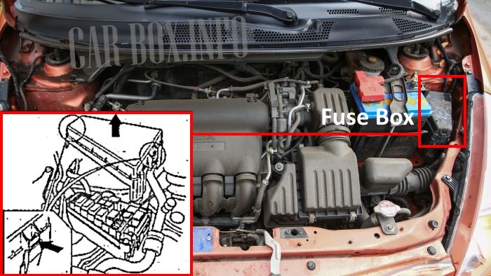
Fuse box located near the battery. To access, you need to squeeze the two latches and pull the cover up.
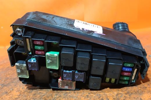
Photo is an example.
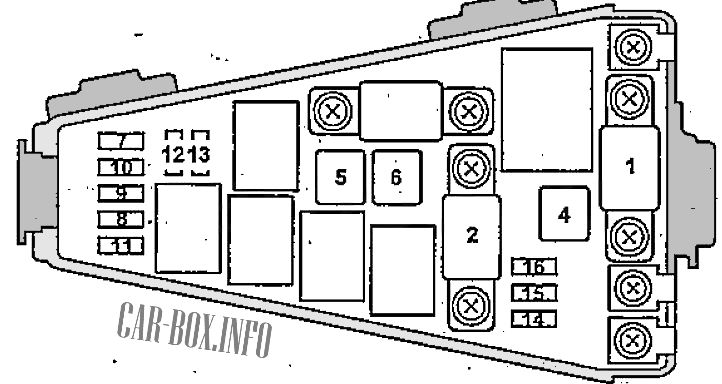
| Diagram | ||
|---|---|---|
|
||
| No. | Description | A |
| 1 | Battery | 80 |
| 2 | EPS electronic control unit | 40 |
| 3 | Ignition switch (+ B) | 50 |
| 4 | Pressure modulator and ABS electronic control unit | 40 |
| 5 | Heater blower motor | 40 |
| 6 | Fuses No. 2, 3, 4, 13, 14 in the cabin | 40 |
| 7 | Sunroof Motor, # 24 Fuse Holder (with Fog Lights), Fog Lamp Diagnostic Connector (YOP) | 30 |
| 8 | Diagnostic socket, "MULTIVISION" system unit (models with navigation system), audio system unit (models without navigation system), TV tuner (models with navigation system), instrument cluster, remote control unit for central locking, luggage compartment lamp, lamp interior lighting, local illumination lamp | 15 |
| 9 | Switch illumination, instrument cluster illumination, fog lamp relay, electronic illumination, air conditioning control unit (with automatic control), illumination of the air conditioning and heater control panel (without automatic system), illumination of the "MULTIVISION" system unit (models with a navigation system), illumination of the audio system unit, front marker lamps, rear marker lamps, license plate light, connector for additional equipment (fuse box) | 10 |
| 10 | Cooling fan motor | 20 |
| 11 |
|
30 |
| 12 | Right headlight | 20 |
| 13 | LH headlight, high beam indicator | 20 |
| 14 | Direction indicator and alarm circuit. (Instrument cluster) | 10 |
| 15 | Pressure modulator and ABS electronic control unit | 30 |
| 16 |
|
10 |
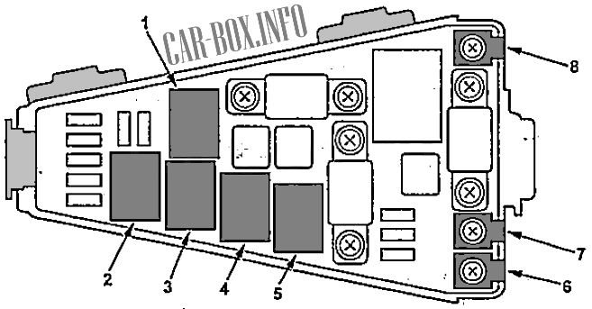
| Relay | ||
|
||
| 2 | A / C compressor electromagnetic clutch relay | |
| 3 | Condenser fan relay | |
| 1 | Headlight relay | |
| 5 | Cooling fan motor relay | |
| 4 | Horn relay | |
| 7 | Starter | |
| 8 | T-101 engine wire harness | |
| 6 | EPS T-102 wire harness | |
