Most of the power circuits of the Japanese crossover electrical equipment are protected by fuses. Powerful consumers are connected via relays. Protective elements are installed in mounting blocks located in the engine compartment, passenger compartment and trunk.

Reviewed the 2nd generation Honda Pilot (YF4) 2008, 2009, 2010, 2011, 2012, 2013, 2014, 2015 models.
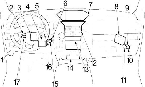
In the passenger compartment
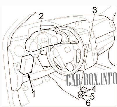
The fuse block is located on the driver's side behind the dashboard (number 1 in the picture). 2 - instrument cluster module. 3,4,5,6 - heaters and sockets relays.
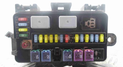
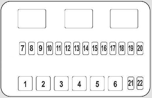
Fuse box
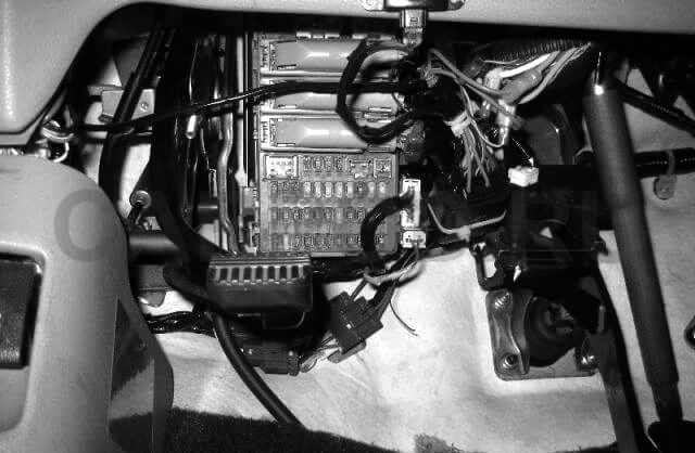
Access example.
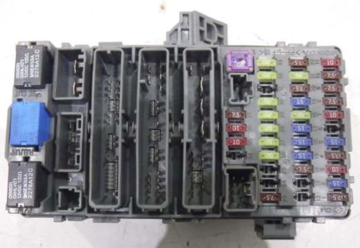
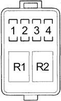
General view of the block.
| Diagram | ||
|---|---|---|

|
||
| No. | Description | A |
| 1 | All-wheel drive system VTM-4 | 7.5 |
| 2 | Fuel pump fuse (Gasoline) | 15 |
| 3 | ACG | 10 |
| 4 | Dynamic stabilization system VSA | 7.5 |
| 5 | Seat heaters | 15 |
| 6 | No | - |
| 7 | Automatic lighting control system | 10 |
| 8 | 7.5 | |
| 9 | ODS | 7.5 |
| 10 | Dashboard | 7.5 |
| 11 | Additional security system | ten |
| 12 | Right daytime running light | ten |
| 13 | Left daytime running light | ten |
| 14 | Low-power lamps (interior lighting) | 7.5 |
| 15 | Low power lamps (outdoor lighting) | 15 |
| 16 | RH low beam headlamp | 15 |
| 17 | Left low beam headlamp | 15 |
| 18 | Main circuit of running lights | 20 |
| 19 | Main fuse for low power lamps | 15 |
| 20 |
|
7.5 |
| 21 | Low beam main circuit | 20 |
| 22 | VBSOL2 | 7.5 |
| 23 | STRLD | 7.5 |
| 24 | No | - |
| 25 | - | |
| 26 | Driver's door window regulator | 20 |
| 27 | HAC OP | 20 |
| 28 | Top hatch electric drive | 20 |
| 29 | Door locks | 20 |
| 30 | Front passenger door window regulator | 20 |
| 31 | No | 30 |
| 32 | Window regulator for the right rear door | 20 |
| 33 | Rear left door window regulator | 20 |
| 34 | No | - |
| 35 | Cruise control | 10 |
| 36 | Power mirrors, AC inverter, air conditioning compressor clutch relay, electrochromic rearview mirror / monitor in the rearview mirror, HVAC control unit, heated front seats relay, cooling fan control relay (diode), front heater relay, relay heated second row seats, optional connector, power window control unit ('09 -'11), cooling fan relay (diode), rear heater relay, climate control unit for rear passengers, heated rear window relay, trailer electrical relay, block body electronics in door (MCU) ('12 -'15) | 10 |
| 37 | Daytime Running Lights | 7.5 |
| 38 | Wiper | 30 |
|
||
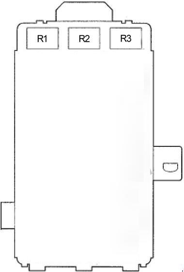
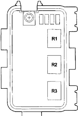
| R1 | Window lifters | |
| R2 | Fuel pump relay | |
| R3 | Starter | |
Separate relays
Additional relays in the passenger compartment.
|
|
| No. | Description |
| 1 | '11 -'15: Tailgate glass relay |
| 2 | '09 -'10: Tailgate glass relay |
| 3 | Side light and reversing lamp control module |
| 4 | Automatic lighting control module |
| 5 | All wheel drive relay (VTM-4) |
| 6 | Front outlet relay |
| 7 | Display control module (audio / navigation / climate control) |
| 8 | Engine cushion control module |
| 9 | High beam relay |
| 10 | Fog light relay |
| 11 | Relay for socket in luggage compartment |
| 12 | Audio control module |
| 13 | Climate control module |
| 14 | Navigation control panel |
| 15 | Ignition Relay (Acc Cut) |
| 16 | Ignition relay (IG2) |
| 17 | Starter relay No. 2 |
|
|
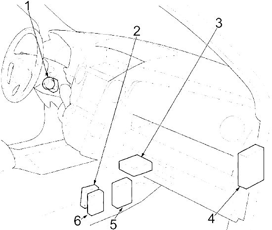
| 1 | Immobilizer control module |
| 2 | USB connector control module |
| 3 | Airbag control module |
| 4 | Audio amplifier |
| 5 | AC inverter control module |
| 6 | HandsFreeLink control module |
In the engine compartment
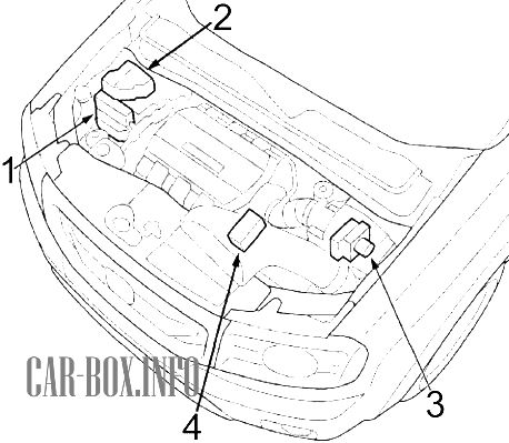
Location of the components:
- PCM module;
- main fuse box;
- exchange rate stabilization system (VSA) module;
- additional fuse box
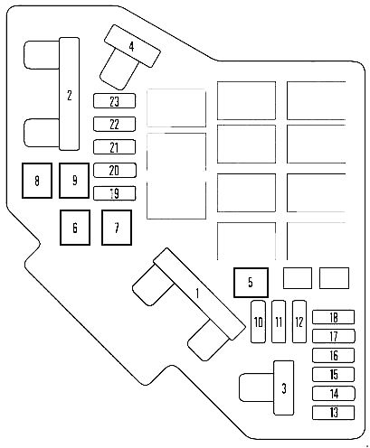
Primary fuse box
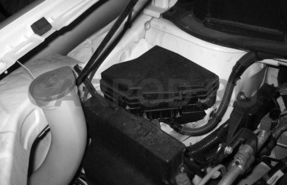
The fuse mounting block is located near the washer reservoir.
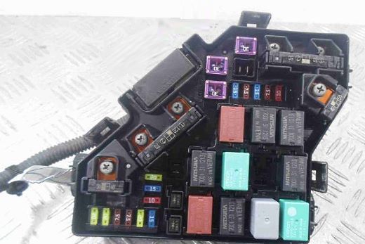
Photo is an example.
| Diagram | |
|---|---|
|
|
| No. | Decoding |
| 1 | No |
| 2 | OP Main |
| IG nutrition | |
| 3 | No |
| 4 | Main headlight circuit |
| Power window fuse | |
| 5 | No |
| 6 | Condenser fan |
| 7 | Cooling fans |
| 8 | Heated rear window |
| 9 | Fan |
| 10 | Front Fog lamps |
| 11 | Additional fan |
| 12 | ACM |
| 13 | Front passenger seat backrest tilt adjustment |
| 14 | Electric fore-and-aft adjustment of the front passenger seat |
| 15 | IGPS Engine oil level |
| 16 | Main beam headlamp circuit |
| 17 | Audio system |
| 18 | Ignition coil |
| 19 | Main fuse |
| 20 | Clutch MG |
| 21 | DBW |
| 22 | Interior lighting |
| 23 | Reversing lights |
| 24 | Main fan diode |
| 25 | Additional fan diode |
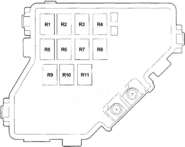
|
|
| R1 | Fan control |
| R2 | Engine mounts (ACM) |
| R3 | Optional Engine Control Unit Relay (PGM-FI Sub) |
| R4 | Ignition coils |
| R5 | Air conditioner fan |
| R6 | Front heater |
| R7 | Heated rear window |
| R8 | A / C Compressor Clutch |
| R9 | Cooling fan |
| R10 | Throttle body (ETCS) |
| R11 | Engine control unit (PGM-FI Main # 1) |
Auxilary fuse box
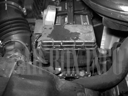
Located near the battery.
General view.
| Diagram | ||
|---|---|---|
|
||
| No. | Protected chain | A |
| 1 | Electric tailgate | 40 |
| 2 | VTM-4 system | 20 |
| 3 | Trailer main circuit | 30 |
| 4 | Relay VSA F / S | 40 |
| 5 | Rear fan | 30 |
| 6 | Dynamic Stability Assist (VSA) motor | 30 |
| 7 | Hazard warning lights | 15 |
| 8 | Electric tailgate closing drive | 20 |
| 9 | Driver's electric backrest tilt adjustment | 20 |
| 10 | Electric adjustment of the longitudinal position of the driver's seat | 20 |
| 11 | Horn, brake lights | 20 |
| 12 | Additional equipment socket at the rear of the center console | 15 |
| 13 | Rear wiper | 10 |
| 14 | Electric trailer braking system | 20 |
| 15 | Inverter A / C | 20 |
| 16 | Socket for connecting additional equipment in the center console | 15 |
| 17 | Trailer battery charging system | 20 |
| 18 |
|
15 |
| 19 | Rear socket for connecting additional electrical equipment | 15 |
| 20 | Tailgate glass motor | 20 |
| 21 | Heated rear seats | 15 |
| 22 | Headlight washer motor | 30 |
|
||
| R1 | Rear wiper | |
| R2 | ||
| R3 | Empty | |
In the luggage compartment
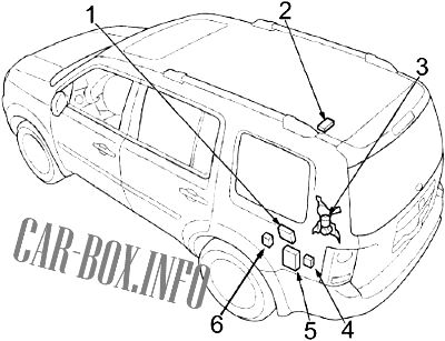
Location of components: 1 - Trunk lid electric control module; 2 - Compass control module; 3 - Electric drive of the trunk lid; 4 - Trailer lighting control module; 5 - Four-wheel drive control module (VTM-4); 6 - the Block of fuses
| Diagram | ||
|---|---|---|
|
||
| No. | Description | A |
| 1 | Direction indicators / trailer alarms | 7.5 |
| 2 | Trailer reversing lamps | 7.5 |
| 3 | Trailer stop lamps | 7.5 |
| 4 | Trailer side lights | 20 |
| Relay | ||
| R1 | Ignition (trailer) | |
| R2 | Trailer lighting | |
