This full-size crossover with a large eight-seater saloon was unveiled by Honda at the 2002 Detroit Auto Show. Unlike the Passport model based on the Isuzu Rodeo, this is the company's own development. The car was built on the same platform as the Acura MDX, but based on a more classic off-road styling. In this material, we will analyze in detail the fuse circuits for Honda Pilot (YF1 body) 1st generation 2002, 2003, 2004, 2005, 2006, 2007, 2008 release.

Here you will find the locations and photos of the fuse blocks. Separately, we note the elements responsible for the cigarette lighter and fuel pump.
In the passenger compartment
From the driver's side
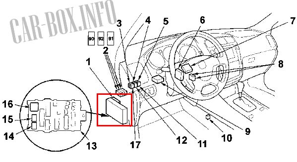
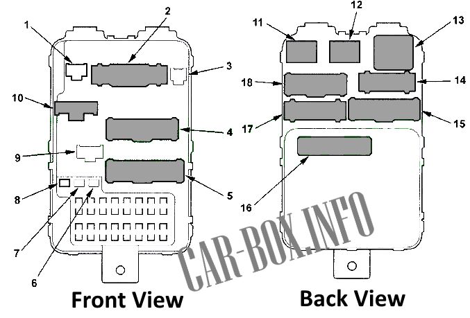
Arrangement of control units: 1 - MULTIPLEX control unit on the driver's side, 2 - auxiliary fuse holders, 3 - sunroof closing relay, 4 - fog lamp relay, 5 - audio system rear amplifier relay (models up to 2004 with "BOSE" audio system), 6 - control unit automatic lighting systems, 7 - daytime lighting control unit (Canadian models), 8 - main injection system relay # 1 and main injection system relay # 2, 9 - tire pressure monitoring system (TPMS) unit (models from 2004 .), 10 - rear heater fan motor relay, 11 - seat heater relay, 12 - size relay, 13 - fuse block under the dashboard on the driver's side, 17 - sunroof opening relay
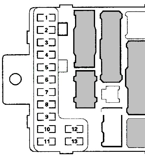
Fuse box
#13 on the picture.

General view.
| Diagram | ||
|---|---|---|
|
||
| No. | Description | A |
| 1 | Honda Pilot Fuel pump fuse, electronic control unit SRS (VA) | 15 |
| 2 | SRS electronic control unit | 10 |
| 3 | A / C compressor magnetic clutch relay, heater fan relay, A / C control panel, A / C control unit, condenser fan motor relay, fan cut-off relay, rear heater fan motor relay, A / C and rear heater control unit, air flow direction change actuator (rear), relay rear window heater, air intake switch | 7.5 |
| 4 | Power mirrors, automatic lighting control unit, compass (models without navigation system), "R" connector (option), external electrochromatic mirrors, mirror heater, seat heater relay | 7.5 |
| 5 | Daytime Lighting Control Module (Canada models) | 10 |
| 6 | Powertrain control unit, VTM-4 relay | 15 |
| 7 | Front passenger position detection system unit, passenger seat sensor | 7.5 |
| 8 | Bodywork power outlet relay, auxiliary connectors, selector lock solenoid valve | 7.5 |
| 9 | Daytime running light control unit, brake light sensor, cruise control main switch indicator, driver's side MULTIPLEX control unit, front seat position control unit, instrument cluster, central locking relay, central locking remote control unit, control unit MUL TIPLEX front passenger side, airbag indicator, rain sensor, (models with automatic wiper control) reversing lamp relay, four-wheel drive control unit (VTM-4), forced four-wheel drive switch, electric windshield washer (models with automatic wiper control), TPMS receiver unit (models from 2004) | 10 |
| 10 | Relay-interrupter for direction indicators and alarm | 7.5 |
| 11 | System unit for changing the operating interval of the rear window wiper, electric drive for the rear window wiper, electric drive for the rear window washer |
10 |
| 12 | Relay for the wiper interval change system, electric windshield washer drive, electric windshield wiper drive (models with automatic wiper control system), automatic wiper control system relay (models with automatic wiper control system) | 30 |
| 13 | No | - |
| Relay | ||
|
||
| 22 | Ignition switch wire | |
| 13 | SRS main connector | |
| 1 | Diode: Driver's door illumination | |
| 2 | Diode: Illumination of the opening of the rear left door | |
| 6 | Connector "A" of the MULTIPLEX control unit, driver's side | |
| 26 | Reversing light relay | |
| 25 | Starter cutout relay | |
| 27 | Relay-interrupter for direction indicators and alarm | |
| 7 | Connector for erasing codes | |
| Rest: either wiring harness or not used | ||
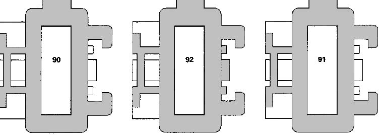
Auxiliary fuse holders
#2 on the picture.
| Diagram | ||
|---|---|---|
|
||
| No. | Description | A |
| 90 |
|
7.5 |
| 91 |
|
|
| 92 |
|
|
From the passenger side

Location of control units. 18 - selector lock solenoid valve relay, 19 - throttle position control unit relay, 20 - air-fuel ratio sensor relay, 21 - audio system amplifier (models from 2004 with "BOSE" audio system), 22 - air conditioning electronic control unit, 23 - receiver for central locking remote control system, 24 - rear window defogger relay, 25 - fuse block under the dashboard on the front passenger side, 26 - MULTIPLEX control unit on the front passenger side, 27 - power window relay, 28 - auxiliary equipment power socket relay , 29 - electronic control unit SRS, 30 - front amplifier of the audio system (models up to 2004), 31 - ignition coil relay.
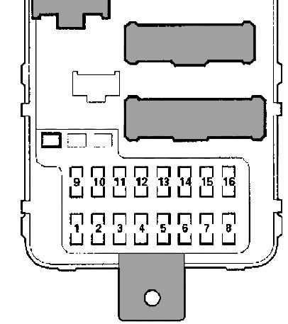
Fuse box
#25 on the picture.
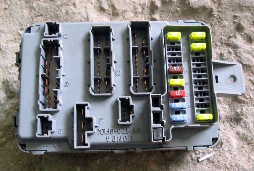
General view.
| Diagram | ||
|---|---|---|
|
||
| No. | Decryption | A |
| 1 | Electric sunroof | 30 |
| 2 | Electric driver's seat cushion rear adjustment, driver's electric backrest tilt adjustment, driver's seat position control unit | 20 |
| 3 | Electric adjustment of the front part of the front passenger seat cushion, electric adjustment of the front passenger seat in the longitudinal direction | 20 |
| 4 | Electric driver's seat cushion front, electric driver's seat longitudinal adjustment, driver's seat position control unit | 20 |
| 5 | Front passenger seat cushion rear adjustment, front passenger seat backrest angle adjustment, passenger side MULTIPLEX control unit | 20 |
| 6 | Daytime Lighting Control Module (Canada models) | 10 |
| 7 | Power window for rear left door, sunroof relay (models up to 2004), sunroof closing relay (models up to 2004) | 20 |
| 8 | Front passenger door power window | 20 |
| 9 | Audio unit, front power outlet for accessories, DVD player (models with DVD system for rear passengers), additional socket for connecting a cell phone (models with DVD system for rear passengers), multifunction display (models without navigation system), electronic navigation unit systems, navigation system display, Honda Pilot cigarette lighter fuse, rear controller and screen (models with DVD system for rear passengers), rear view camera control unit (models with navigation system) | 15 |
| 10 | Automatic transmission selector position indicator panel, audio system unit illumination, air conditioning control panel illumination, cruise control master switch illumination, illumination rheostat, individual settings memory switch illumination, MULTIPLEX control unit on the driver's side, DVD player unit, glove box illumination, switch illumination fog lights, instrument cluster illumination, hazard warning switch illumination, interior illumination switch illumination, front marker lamps, side marker lamps (left), license plate illumination, sunroof control switch, multifunction display illumination, navigation system electronic unit illumination, navigation system electronic unit, connector "T" (option), front passenger airbag indicator,front side marker lamps, right-hand side, illumination of the seat heater switch, size relay, trailer connector, illumination of the forced connection switch for four-wheel drive, interior lighting lamps (models since 2004) | 15 |
| 11 | Luggage compartment light, door opening lights, multifunction display (models without navigation system), navigation electronics, vanity mirror lights, front and rear spotlights, footwell lights (models from 2004), TPMS receiver unit ( models from 2004) | 10 |
| 12 | Front passenger side MULTIPLEX control unit | 20 |
| 13 | Automatic lighting control unit, MULTIPLEX control unit in the driver's door, driver's seat position control unit, driver's side MULTIPLEX control unit, memory system indicator, instrument cluster, electronic immobilizer control unit, immobilizer indicator, central locking remote control unit, Navigation electronics, passenger side MULTIPLEX control unit, rear view camera control unit (models with navigation system), anti-theft indicator | 7.5 |
| 14 | Seat heaters | 20 |
| 15 | MUL TIPLEX control unit in the driver's door, electronic control unit for power windows, sunroof opener relay (models from 2004), sunroof closing relay (models from 2004) | 7.5 |
| 16 | Power window regulator, rear right door | 20 |
| Relay | ||
|
||
| 12 | Accessory power outlet relay | |
| 6 | (For air conditioner) | |
| 7 | Illumination of the opening of the rear right door | |
| 8 | Illumination of the front passenger door opening | |
| 16 | Connector "A" of the MULTIPLEX control unit, passenger side | |
| 11 | Power window relay | |
| 13 | Heated rear window relay | |
| Rest: either wiring harness or not used | ||
In the engine compartment
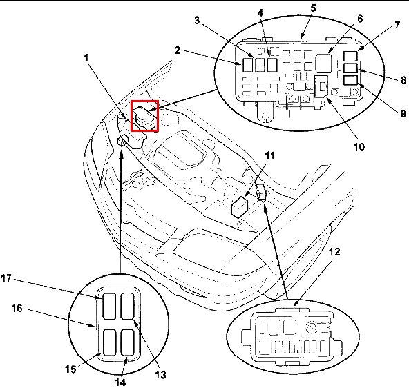
Location of blocks and control units in the engine compartment.
- 1 - powertrain control unit,
- 2 - 10: relay in the main fuse box.
- 11 - control unit for the stability control system,
- 12 - additional fuse box in the engine compartment,
- 16 - relay block in the engine compartment.
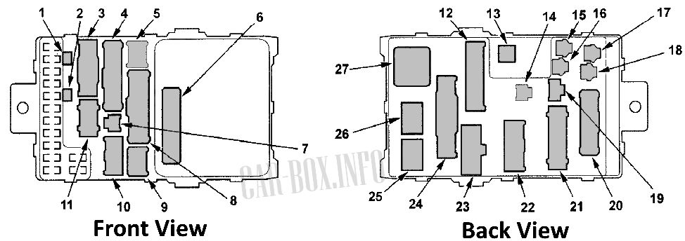
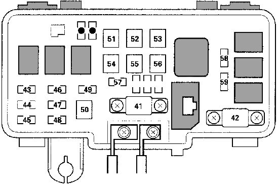
Primary fuse box
#2-10 on the picture above.
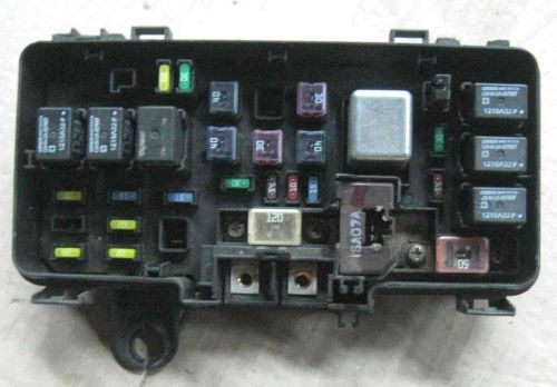
General form.
| Diagram | ||
|---|---|---|
|
||
| # | Description | A |
| 41 | Battery, power supply system | 120 |
| 42 | Ignition switch (BAT), "U" connector (option) | 50 |
| 43 | Daytime Lighting Control Module (Canada models), headlamp (right), fog lamp relay | 20 |
| 44 | No | - |
| 45 | Daytime Running Light Control Module (Canada models), Headlamp Switch Relay, Headlamp (LH), High Beam Indicator | 20 |
| 46 | Diagnostic connector (DLC), injectors, main injection system relay # 1, camshaft position sensor, crankshaft position sensor "A", crankshaft position sensor "B" | 15 |
| 47 | Brake lights, driver side MULTIPLEX control unit, horn (high tone), ignition switch, # 90 fuse (# 1 auxiliary fuse holder), powertrain control unit, trailer connector, stability control unit (VSA) | 20 |
| 48 | Audio system (models without DVD system for rear passengers), front audio system amplifier (models up to 2004), rear audio system amplifier (models up to 2004), audio system amplifier (models from 2004) | 20 |
| 49 | Alarm | 15 |
| 50 | Fog lights | 20 |
| 51 | Fuses No. 1, 7, 8, 15, 16 of the mounting block under the dashboard from the front passenger side, power window relay | 40 |
| 52 | Rear heater blower motor | 30 |
| 53 | Heated rear window | 30 |
| 54 | Fuses # 9, 10, 11, 12 and 13 of the block under the dashboard from the front passenger side | 40 |
| 55 | Fuses # 2, 3, 4, 5, 6 and 14 of the block under the dashboard from the front passenger side | 40 |
| 56 | Heating fan relay | 40 |
| 57 | Cooling fan motor | 30 |
| 58 | Condenser fan motor | 30 |
| 59 | A / C Compressor Electromagnetic Clutch | 7.5 |
| Relay | ||

|
||
| 8 | air conditioning compressor electromagnetic clutch | |
| 5 | heater fan motor | |
| 6 | condenser fan motor | |
| 3 | Diode | |
| 9 | Supply voltage monitoring system unit | |
| 4 | horn | |
| 1 | Headlight relay No. 1 | |
| 2 | Headlight relay No. 2 | |
| 7 | cooling fan motor | |
| Rest: either wiring harness or not used | ||
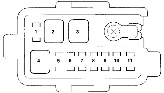
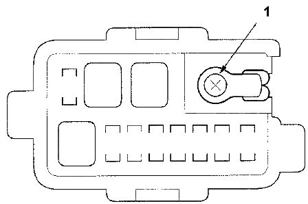
Additional fuse box
#12 on the picture.

General view.
| Diagram | ||
|---|---|---|
|
||
| No. | Description | A |
| 1 |
|
20 |
| 2 | Vehicle stability control (VSA) control unit (+ B FSR) | 40 |
| 3 | Vehicle stability control (VSA) control unit (+ B MTR) | 30 |
| 4 |
|
20 |
| 5 | No | - |
| 6 | Rear accessory power outlet | 20 |
| 7 | Throttle position control unit | 15 |
| 8 | Ignition coils | 15 |
| 9 | Air fuel ratio sensors (B1, B2), air fuel ratio sensor relay, cooling fan motor relay, engine mount control solenoid valve, EVAP accumulator solenoid valve, auxiliary oxygen sensor (B1, B2), supply voltage monitoring system unit (models with 2004 g.) | 15 |
| 10 | Powertrain control unit | 7.5 |
| 11 | Power window control unit | 20 |
| Note : * 1 - models up to 2004; * 2 - models from 2004 | ||
|
||
| 1 | T5 starter wiring | |
