The fourth-generation Accent was unveiled at the 2010 Beijing Motor Show. Compared to its predecessor, it has lengthened by 60 mm (to 4340 mm), became wider by 5 mm (1700) and lower by 10 mm (1460). In this article we will understand in detail fuse box diagrams Hyundai Accent (fourth generation; index RB) 2011, 2012, 2013, 2013, 2014, 2015, 2016 and 2017 years of manufacture.

Here you will find the locations and photos of the mounting blocks. Also, we will separately mark the fuses responsible for the cigarette lighter and the fuel pump.
In the engine compartment
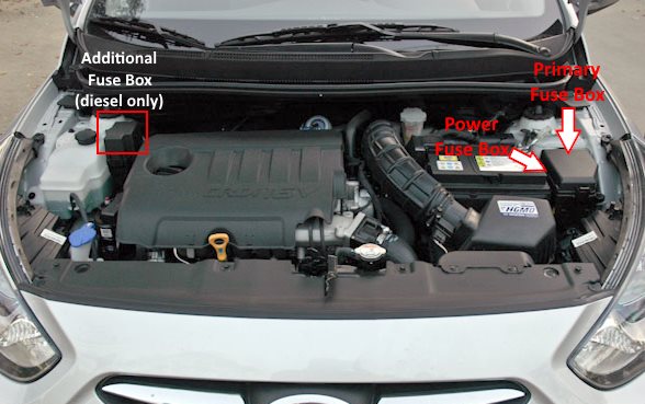
Depending on the engine (diesel or petrol), there may be two or three units under the bonnet.
Primary fuse box

Located on the right side of the engine compartment next to the battery.
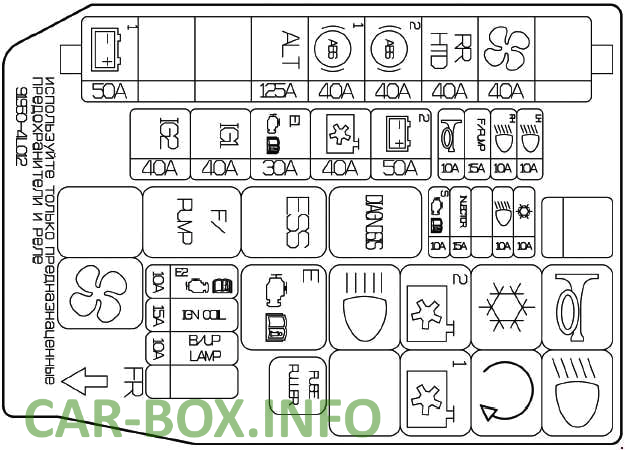
Example of a schematic from the block cover.
| Diagram | ||
|---|---|---|
|
||
| No. | Circuit Protected | A |
| 1 | Spare | - |
| 2 | Spare | - |
| 3 | F / PUMP - Fuel pump fuse | 15 |
| 4 | HORN - Sound signal (Beep) | 10 |
| 5 | B + 2 - Switching unit: emergency gang, power windows, central locking, fuses - F23-F25, F31, F32 | 50 |
| 6 | C / FUN - Heating system control unit | 40 |
| 7 | ECU 1 - Engine control unit - relay 1. Fuse F25 | 40 |
| 8 | IG1 - Ignition switch, body electrical control module, automatic transmission lock control module, start/stop button control module. | 40 |
| 9 | IG2 - Ignition switch, body electrical control module, automatic transmission lock control module, start/stop button control module | 50 |
| 10 | A / CON - Air conditioner | 10 |
| 11 | Spare | - |
| 12 | Spare | - |
| 13 | INJECTOR - Engine control module. Transmission control module. Fuel pump relay. Oil control valve | 15 |
| 14 | Sensor - Engine control module. Camshaft sensor. Oxygen sensor. Immobilizer. Air conditioner - relay. Fan - low speed relay and high speed relay. Solenoid valve | 10 |
| 15 | ECU 2 - Electronic engine control unit | 10 |
| 16 | Reserve | - |
| 17 | B / UP LP - Transmission control unit. Automatic transmission sensor. Dashboard. Combined rear lights. | 10 |
| 18 | WIPER - Glass cleaner | 10 |
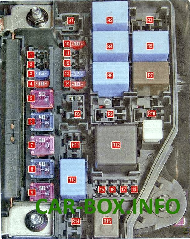
| R1 | Spare | |
| R2 | Horn relay | |
| R3 | Ignition switch relay, body electrical control module, automatic transmission lock control module, engine start and stop button control module | |
| R4 | Air conditioner relay | |
| R5 | Ignition interlock switch relay | |
| R6 | Fan relay (low speed) | |
| R7 | Fan relay (high speed) | |
| R8 | Diagnostic connector relay | |
| R9 | Ignition switch relay | |
| R10 | Ignition switch relay, body electrical control module, automatic transmission lock control module, engine start and stop button control module | |
| R11 | Emergency brake warning relay | |
| R12 | Relay, electronic engine control unit | |
| R13 | Fuel pump relay | |
| R14 | Reserve | |
| R15 | Cooling system radiator fan relay | |
Additional block
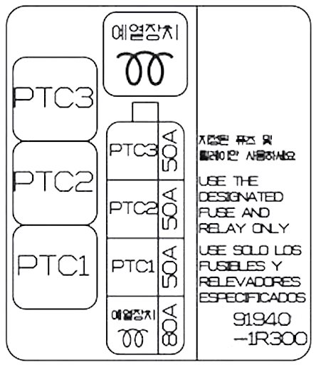
Installed on diesel engine vehicles only.
Power fuse box
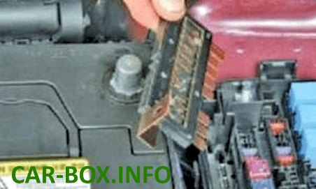
It is mounted on the side of the main unit and consists of high power fusible links.
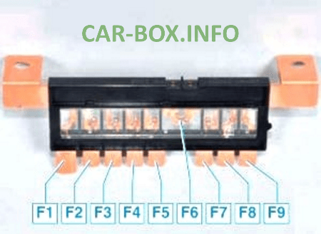
- F1 - Rear light relay 50 A;
- F2 - Spare;
- F3 - Spare;
- F4 - Alternator 125 A;
- F5 - ABS module, diagnostic connector 40 A;
- F6 - ABS module 40 A;
- F7 - Rear window defogger relay 40 A;
- F8 - Fan relay 40 A;
- F9 - Spare.
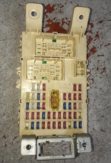
In the passenger compartment

Located under the dashboard on the driver's side. Remove the protective cover for access.
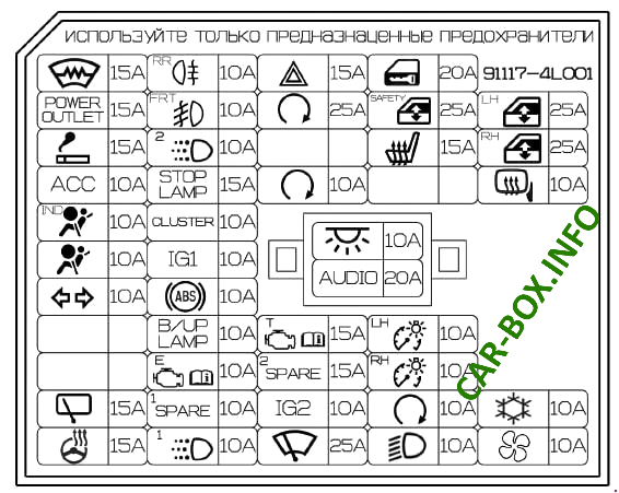
Example of a diagram from the block cover.
General view of the Hyundai Accent IV interior fuse box.
| Diagram | ||
|---|---|---|

|
||
| No. | Description | Amps |
| 1 | FRT-Deicer - Heated windshield | 15 |
| 2 | P / OUTLET - 12V socket | 15 |
| 3 | C / LIGHTER - Accent cigarette lighter fuse | 10 |
| 4 | ACC - Ignition switch - audio system, body electrical control module, automatic transmission lock control module, electronic key system control unit | 10 |
| 5 | A / BAG IND - Airbag deactivation indicator - front | 10 |
| 6 | A / BAG - Airbags, SRS control module | 10 |
| 7 | T / SIG Emergency light | 10 |
| 8 | Spare | - |
| 9 | Spare | - |
| 10 | R / WPR - Rear Window Wiper - Engine, Multi Function Switch | 15 |
| 11 | Spare | - |
| 12 | RR (R / FOG) - Fog lights (rear) | 10 |
| 13 | FRT (F / FOG) - Fog lights (front) | 10 |
| 14 | ROOM 2 - Battery saving relay (automatic protective shutdown) | 10 |
| 15 | STOP LP - Stop lights | 15 |
| 16 | CLUSTER - Instrument Cluster | 10 |
| 17 | IG1 1 - Security system control module | 10 |
| 18 | ABS - hydro electronic ABS module | 10 |
| 19 | B / UP LP - Rear running lights (switch) | 10 |
| 20 | PCU - body electrical control module, automatic transmission lock control module, electronic key system control unit | 10 |
| 21 | H / LP LH - Headlamp - left | 10 |
| 22 | DAY TIME RUNNING LIGHT - Daytime running lights | 10 |
| 23 | HAZARD - Alarm switch | 15 |
| 24 | SMK 1 - Control module, body electrical control module, automatic transmission lock control module, electronic key control module | 25 |
| 25 | Spare | - |
| 26 | SMK 2 - Control module, body electrical control module, automatic transmission lock control module, electronic key control unit, engine start and stop pushbutton switch | 10 |
| 27 | TCU - Speed sensor, automatic transmission range sensor. Pulse generator | 15 |
| 28 | IGN COIL - Ignition coil 1-4, capacitor | 15 |
| 29 | IGN 2 - Power windows. Sunroof | 10 |
| 30 | F / WPR - Windshield wiper | 25 |
| 31 | DOOR LOCK - Central locking - control unit | 20 |
| 32 | SAFETY P / WDW - Power windows - locking | 25 |
| 33 | S / HEATER - Heated front seats | 15 |
| 34 | Spare | - |
| 35 | ROOM 1 - Interior lighting. Air conditioning | 10 |
| 36 | AUDIO - Audio system | 20 |
| 37 | TAIL LH - Headlight and lantern on the left side. License plate illumination | 10 |
| 38 | TAIL RH - Headlight and lantern on starboard side. Illuminated switches, switches in the cab, selector lever. Instrument panel, switch and switch buttons | 10 |
| 39 | START - Starter - relay. Anti-theft alarm | 10 |
| 40 | H / LP RH - Headlamp - right | 10 |
| 41 | P / WDW LH - Power windows control unit - left rear switch | 25 |
| 42 | P / WDW RH - Power windows control unit - switch right rear | 25 |
| 43 | HTD MIRR - Heating system for outside rear-view mirrors | 10 |
| 44 | A / CON 2 - Air conditioner | 10 |
| 45 | Spare | - |

Relays on the back of the unit.
- MK1 - Rear window heating relay;
- MK2 - Fog lamps;
- MK3 - Fog lights;
- MK4 - Side lamps;
- MK5 - Interior lighting relay;
- MK6 - Heated windshield relay;
- MK7 - Central locking relay;
- MK8 - Spare;
- MK9 - Spare;
- MK10 - Alarm relay;
- MK11 - Power windows;
- MK12 - Spare;
- MK13 - Electronic brake signal control relay (mounted outside the unit)

Good