The Mazda CX-7 is the production version of the MX-Crossport concept. Production began in spring 2006 at the plant in Hiroshima, Japan. In 2009, the car underwent a restyling. In this material we will understand in detail the fuse box diagrams Mazda CX-7 (body index ER) 2006, 2007, 2008, 2009, 2010, 2011, 2012 year of manufacture.

Here you will find the locations and photos of the mounting blocks. Also, we will separately mark the fuses responsible for the cigarette lighter and the fuel pump.
In the underhood
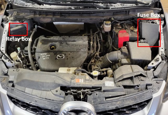
In the engine compartment there is a main fuse box near the battery and an additional relay box.
Main fuse box

The plastic cover must be lifted to gain access to the unit.
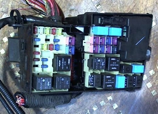
The photo is an example.
| Diagram (Version No. 1) | |
|---|---|

|
|
| No. / Amps | Description |
| Fuses | |
| 1 (10 A) | Turn indicators and signaling |
| 2 (25 A) | Engine management system |
| 3 (20 A) | Horns |
| 4 (10 A) | Brake lights |
| 5 (20 A) | Power windows |
| 6 (15 A) | Mass air flow sensor, exhaust gas recirculation system valve |
| 7 (10 A) | Engine management system |
| 8 (7.5 A) | Electronic engine control unit |
| 9 (15 A) | Headlight washer |
| 10 (15 A) | High beam |
| 11 (20 A) | Throttle control pedal position sensor |
| 12 (10 A) | Air conditioning A/C |
| 13 (15 A) | Parking lights - TNS, license plate illumination lights |
| 14 (15 A) | Dipped beam (left headlamp unit) |
| 15 (15 A) | Dipped beam (right headlamp unit) |
| 16 (30 A) | Heated tailgate glass |
| 17 (20 A) | Fog lights |
| 18 (30 A) | Fuel pump fuse |
| 19 (30 A) | Power windows |
| 20 (20 A) | central locking |
| 21 (30 A) | Engine management system |
| 22 (30 A) | Audio system |
| 23 (20 A) | Sunroof |
| 24 (30 A) | Fuel injectors |
| 25 (40 A) | Seat adjustment |
| Relay | |
| R1 | Injection system (Injector relay) |
| R2 | Fuel pump relay |
| R3 | Main (left) cooling fan |
| R4 | Air blower fan |
| R5 | Additional (right) cooling system fan |
| R6 | Starting system |
| R7 | Fuel pump relay (CIRCUIT) |
| R8 | Main relay |
| R9 | Starting system |
| R10 | Back-up light |
| R11 | Headlight |
| R12 | Throttle control pedal |
| R13 | Parking lights, license plate lights (TNS relay) |
| R14 | Heated tailgate glass |
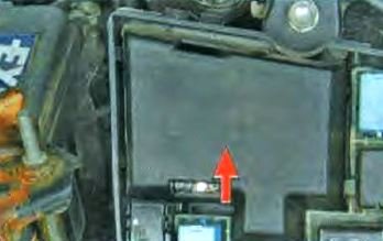
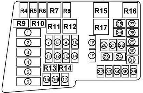
The power fuses are installed in the mounting block under a separate cover.
|
|
| Diagram (Version No. 2) | ||
|---|---|---|
|
||
| No. | Description | Amps |
| 1 | Ignition system | 40 |
| 2 | Fan motor | 40 |
| 3 | Protection of various electrical circuits | 60 |
| 4 | Radiator fan | 40 |
| 5 | Ignition system | 40 |
| 6 | Radiator fan | 40 |
| 7 | Electrically powered seat | 40 |
| 8 | Fuel injection system | 30 |
| 9 | Sunroof | 20 |
| 10 | Bose audio system | 30 |
| 11 | ENGINE - Engine management system | 30 |
| 12 | D.LOCK - Electric locks | 20 |
| 13 | P.WIND - Power windows | 30 |
| 14 | Fuel pump fuse | 30 |
| 14 | IG KEY2 - Ignition system | 40 |
| 15 | ABS1 - ABS system | 40 |
| 16 | ABS2 - ABS system | 20 |
| 17 | DSC system | 7.5 |
| 18 | FOG - Fog lights | 20 |
| 19 | DEF - Rear window heater | 30 |
| 20 | TNS - Parking light, license plate light, entrance system light | 15 |
| 21 | A/C - Air conditioning | 10 |
| 22 | ETC - Accelerator pedal position sensor | 20 |
| 23 | H/LH1 — Headlight corrector | 15 |
| 24 | DRL - Daytime running lights | 15 |
| 25 | H/L LO LH - Right dipped beam headlamp | 15 |
| 26 | H/L LO LH - Left dipped beam headlamp | 15 |
| 27 | ENG BAR 2 - PCM (Power Distribution Module) | 7.5 |
| 28 | ECM - Engine Management System | 10 |
| 29 | ENG BAR 1 - Air flow meter, EGR valve | 15 |
| 30 | RWIND2 - Electric power windows | 20 |
| 31 | STOP - Stop lights | 10 |
| 32 | HORN - Horn | 20 |
| 33 | ENGB+ - PCM (Power Distribution Module) | 25 |
| 34 | HAZARD - Hazard warning lights, direction indicators | 10 |
| R4 | Rear window heater relay | |
| R5 | Light bulb circuit control relay | |
| R6 | Drive-by-wire relay | |
| R7 | Headlight relay | |
| R8 | Backup headlight relay | |
| R9 | Fuel pump relay | |
| R10 | Starter relay #2 | |
| R11 | Cooling fan relay #2 | |
| R12 | Fan relay | |
| R13 | Fuel pump speed control relay | |
| R14 | Injector relay | |
| R15 | Starter relay #1 | |
| R16 | Main relay | |
| R17 | Cooling fan relay #1 | |
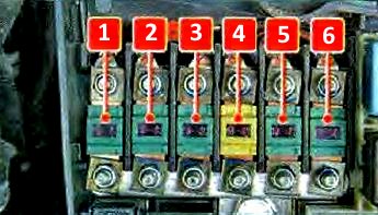
Relay box
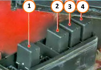
Arrangement of elements in the block: 1 - rear fog lamp relay; 2 - fog lamp relay; 3 - air conditioner relay; 4 - horn relay
In the passenger compartment
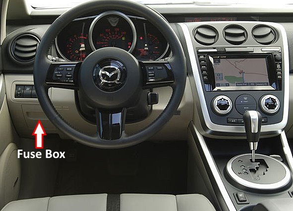
It is located on the driver's side, behind the protective cover.

To replace the fuses in the mounting block located in the passenger compartment of the vehicle, do the following.
1. Pull the cover of the unit toward you....

2. ...and, overcoming the resistance of the catches, remove the cover of the mounting block.

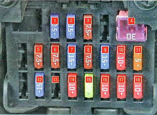
General view of the Mazda CX7 interior fuse box.
| Diagram (Version No. 1) | ||
|---|---|---|

|
||
| No. | Description | Amps |
| 1 | Power windows | 30 |
| 2 | Additional electrical outlet in the passenger compartment, Mazda CX-7 cigarette lighter fuse | 15 |
| 3 | Electric mirror | 7.5 |
| 4 | Additional electrical outlet | 15 |
| 5 | Not used | - |
| 6 | Windshield cleaner and washer | 30 |
| 7 | Rear view mirror heater | 7.5 |
| 8 | Air flow meter, EGR valve | 7.5 |
| 9 | Power windows | 15 |
| 10 | Advanced passive safety system, airbags | 7.5 |
| 11 | Engine management system | 15 |
| 12 | Instrument cluster | 15 |
| 13 | Instrument panel illumination | 10 |
| 14 | Audio system, overhead interior lighting | 15 |
| 15 | Seat heater | 20 |
| 15 | Rear fog lights | |
| 16 | Air conditioner | 10 |
| 16 | Security alarm system | |
| 17 | Seat heater | 20 |
| 18 | Air conditioner | 10 |
| 19 | Rear wiper and washer | 10 |
| Diagram (Version No. 2) | |
|---|---|
|
|
| No. / Amps | Decoding |
| 1 (15 A) | Socket for connection of optional equipment in the passenger compartment, cigarette lighter fuse (OUTLET1) |
| 2 (15 A) | Socket for connection of optional equipment in the luggage compartment (OUTLET2) |
| 3 (7.5 A) | Rear view mirror adjustment - P.MIR |
| 4 (30 A) | Windshield wiper and washer - WIPER |
| 5 (7.5 A) | Heated tailgate glass |
| 6 (7.5 A) | Mass Air Flow Sensor, Exhaust Gas Recirculation (EGR) Valve |
| 7 (15 A) | Power widnows |
| 8 (7.5 A) | Airbags A/B |
| 9 (15 A) | Engine management system - ENGINE |
| 10 (10 A) | Dashboard combination |
| 11 (5 A) | Security alarm system |
| 12 (15 A) | Interior lighting - ROOM |
| 13 | Not used |
| 14 (10 A) | Instrument panel illumination |
| 15 (20 A) | Heated seats SEAT |
| 16 (10 A) | Air conditioning - A/C |
| 17 (10 A) | Tailgate window wiper and washer |
| 18 (10 A) | Rear fog light |
