The fourth generation of the Mercedes-Benz S-Class was presented at the Paris Motor Show in 1998. The creator of the model was Steve Mattin. In 2002, the car went through a restyling. In this article we will understand in detail fuse box diagrams Mercedes W220 (4th Gen; S-Class: S280, S320, S350, S430, S500, S600, S55 AMG, S63 AMG, S65 AMG, S320 CDI, S400 CDI) 1998, 1999, 2000, 2001, 2002, 2003, 2003, 2004, 2005 years of manufacture.
Here you will find the locations and photos of the mounting blocks. Also, we will separately mark the fuses responsible for the cigarette lighter and the fuel pump.
In the engine compartment
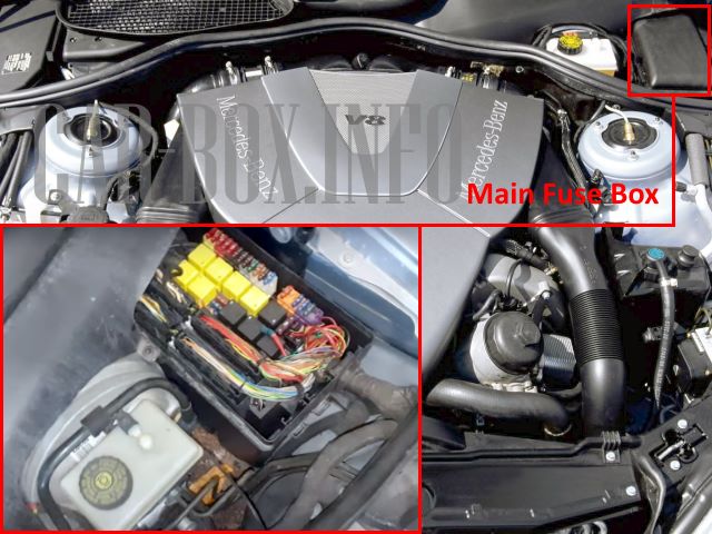
The main mounting block is located on the driver's side.
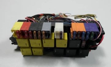
General view of the main unit.
| Diagram | ||
|---|---|---|
Models after 2002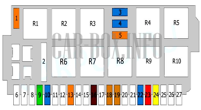
|
||
Models up to 2002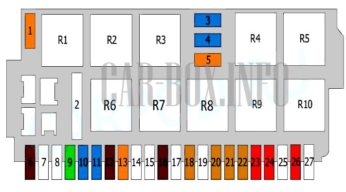
|
||
| No. | Relay description | |
| R1 | Windshield wiper de-icing relay | |
| R2 | Terminal 15 relay | |
| R3 | Terminal 15R relay | |
| R4 | steering column adjustment 1/2, horizontal | |
| R5 | ||
| R6 | high pressure headlamp washer | |
| R7 | Wiper high / low relay | |
| R8 | wiper | |
| R9 | steering column adjustment 1/2, vertical | |
| R10 | ||
| No. | Fuse decoding | A |
| 1 | Windshield wiper de-icing relay | 40 |
| 2 | High pressure headlamp washer relay | 50 |
| 3 | Steering column adjustment, horizontal | 15 |
| 4 | Steering column adjustment, vertical | 15 |
| 5 | Wiper relay | 40 |
| 6 | Heater switch (up to 2002) | 7.5 |
| Not used (after 2002) | - | |
| 7 | Empty | - |
| 8 | Empty | - |
| 9 | Air suspension | 30 |
| ADS control unit | ||
| Body control unit | ||
| 10 | Windshield washer pump | 15 |
| 11 | mercedes w220 front cigarette lighter fuse (before 2002) | 15 |
| Ashtray illumination (up to 2002) | ||
| Not used (after 2002) | - | |
| 12 | Automatic location recognition (up to 2002) | 7.5 |
| Seat belt buckle warning light (up to 2002) | 7.5 | |
| Not used (after 2002) | - | |
| 13 | Front left door control unit | 40 |
| 14 | Empty | - |
| 15 | Empty | - |
| 16 | Stop lamp switch | 7.5 |
| 17 | - | |
| 18 | Telephone | 5 |
| Emergency call system | ||
| 19 | Seat belt pretensioner (after 2002) | - |
| 5 | ||
| 20 | Diagnostic connector (up to 2002) | 5 |
| Instrument panel (before 2002) Not used (after 2002) |
- | |
| 21 | Instrument panel (before 2002) Not used (after 2002) |
5 |
| - | ||
| 22 | Instrument panel (up to 2002) | 5 |
| Audio system (after 2002) | 15 | |
| Radio remote display (after 2002) | ||
| 23 | Climate control (up to 2002) | 10 |
| Air conditioning control unit (up to 2002) | ||
| TV tuner (after 2002) | ||
| CD changer (after 2002) | ||
| 24 | Diagnostic connector (up to 2002) | 10 |
| Audio system (after 2002) | 20 | |
| Center console (after 2002) | ||
| 25 | Not used (before 2002) Audio amplifier (after 2002) |
- |
| 25 | ||
| 26 | Top control panel module (before 2002) Not used (after 2002) |
10 |
| 27 | Empty | - |
Additional fuse box
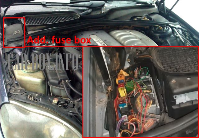
The auxiliary unit is located on the passenger side.
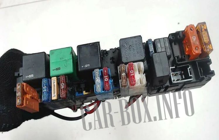
General view.
| Diagram | ||
|---|---|---|
|
||
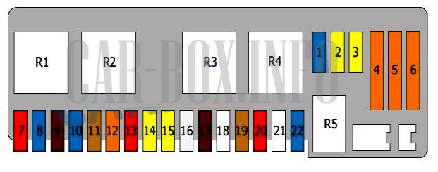
| No. | Relay | |
| R1 | Relay motor electronics | |
| R2 | Starter | |
| R3 | Engine control unit, diesel | |
| Or | ||
| Air pump | ||
| R4 | Air compressor relay | |
| R5 | horn relay | |
| No. | Circuit breakers | A |
| 1 | horn (beep) | 15 |
| 2 | Relay motor electronics | 20 |
| 3 | 20 | |
| 4 | Secondary air pump relay | 40 |
| 5 | Air compressor relay | 40 |
| 6 | Heating system | 40 |
| 7 | Traction control unit - until 2002 | 5 |
| Traction control unit - after 2002 | 10 | |
| 8 | Heated steering wheel (after 2002) | 15 |
| Empty(until 2002) | - | |
| 9 | Daylight system | 7.5 |
| 10 | Transmission control unit / Automatic transmission shift lever | 15 |
| 11 | Opening the luggage compartment | 5 |
| 12 | Door control unit, front right | 40 |
| 13 | Xenon lamps | 10 |
| Headlight adjustment | ||
| 14 | Additional heater | 20 |
| 15 | Relay, additional air unit | 20 |
| 16 | Engine Control Unit, Diesel / Starter Relay | 25 |
| 17 | Engine control unit, diesel / intake manifold heater | 7.5 |
| 18 | Empty | - |
| 19 | Body Control Unit / ADS Control Unit / Air Suspension | 5 |
| 20 | Relay, auxiliary air unit / A / C control unit / Fan control | 10 |
| 21 | Cooling fan control unit or not used (before 2002) | 7.5 |
| Empty (after 2002) | - | |
| 22 | Ignition coils and capacitor | 15 |
Additional block #2 (only cars after 2002)
Vehicles after 2002 model year are equipped with another mounting block.
| Diagram | ||
|---|---|---|
|
||
| No. | Decryption | A |
| R1 | Motronic system | |
| R2 | Charge air relay | |
| R3 | Relay of the fuel module in the tank (fuel pump relay) or Empty |
|
| 1 | Motronic system | 20 |
| 2 | Motronic system | 20 |
| 3 | Not | |
| 4 | Charge air relay | 10 |
| 5 | Not | |
In the passenger compartment
Here there are two units responsible for the protection of the vehicle's electrical circuits.
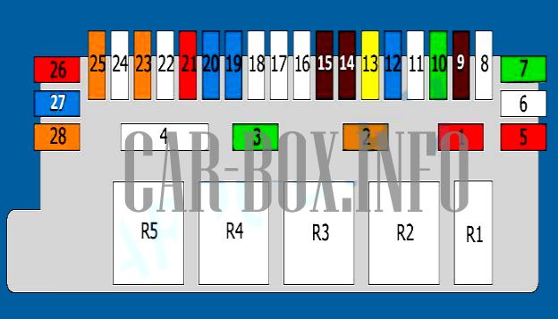
First unit
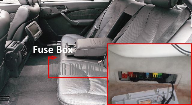
Fuse box #1 is located under the rear passenger seat.
| Diagram | ||
|---|---|---|
|
||
| No. | Description | |
| R1 | Rear window curtain relay | |
| R2 | Traction sensor relay | |
| R3 | Terminal 15 relay | |
| R4 | Additional fuel pump relay | |
| R5 | Rear window heater relay | |
| No. | Description | A |
| 1 | Rear window curtain relay | 10 |
| 2 | Traction sensor | 5 |
| 3 | Additional fuel module relay (Mercedes w220 fuel pump fuse) | 30 |
| 4 | Rear window heater relay | 50 |
| 5 | Trailer control unit | 10 |
| 6 | Trailer connector | 25 |
| 7 | Trailer control unit | 30 |
| 8 | Closing the luggage compartment | 25 |
| Luggage compartment release relay | ||
| 9 | Keyless go control unit | 7.5 |
| 10 | Control unit (for cab) | 30 |
| 11 | Empty | - |
| 12 | Voice control unit | 15 |
| Handsfree phone | ||
| 13 | Pneumatic System Equipment (PSE) | 20 |
| 14 | Telephone | 7.5 |
| 15 | Multifunctional control unit | 7.5 |
| Antenna amplifier | ||
| 16 | - | |
| 17 | Sound amplifier | 25 |
| 18 | rear power seats | 25 |
| 19 | Rear air conditioner | 15 |
| Coolant circulation pump | ||
| 20 | Rear air conditioner | 15 |
| 21 | Tire pressure monitoring system control unit | 10 |
| 22 | Front left seat belt pretensioner | 25 |
| 23 | Door control unit, rear left | 40 |
| 24 | Front right seat belt pretensioner | 25 |
| 25 | Door control unit, rear right | 40 |
| 26 | Parktronic system | 10 |
| 27 | Refrigerator (in the rear seat backrest) | 15 |
| 28 | Top console (in the ceiling) | 40 |
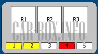
Second unit
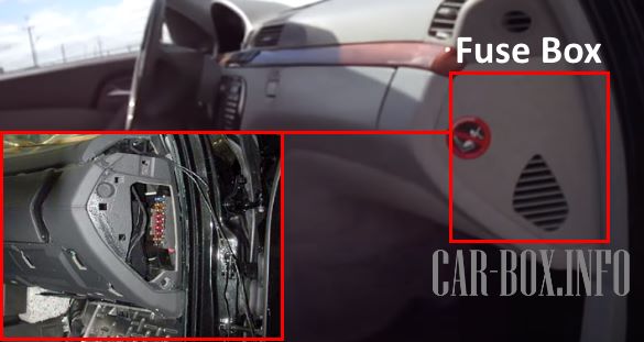
Located in the end of the dashboard on the passenger side, behind the cover protection.
| Diagram | ||
|---|---|---|
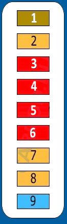
|
||
| No. | Decryption | A |
| 1 | Steering column control unit | 7.5 |
| engine control unit | ||
| EIS control unit | ||
| Alarm | ||
| 2 | Instrument Panel | 5 |
| 3 | Top Control Panel Module | 10 |
| 4 | Diagnostic connector (DLC) | 10 |
| 5 | Climate control | 10 |
| Air conditioner control unit | ||
| 6 | Center console | 10 |
| 7 | Diagnostic connector (DLC) | 5 |
| Instrument Panel | ||
| 8 | Instrument Panel | 5 |
| 9 | Front cigarette lighter fuse | 15 |
| Ashtray illumination | ||
