L200 is a pickup truck produced by Mitsubishi Motors since 1978. The modern model (since 2006) is sold in some countries under the name Triton. It is available in two-door single cab, two-door four-seat cab (Club Cab) and four-door five-seat cab (Double Cab). In this article we will understand in detail fuse box diagrams Mitsubishi L200 / Triton (fouth generation) 2005, 2006, 2007, 2008, 2009, 2010, 2011, 2012, 2013, 2014, 2015 years of manufacture.
Here you will find the locations and photos of the mounting blocks. Also, we will separately mark the fuses responsible for the cigarette lighter and the fuel pump.
In the engine compartment
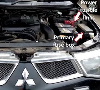
Location of components.
Power fusible links
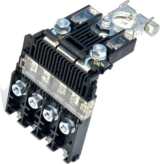
Next to the battery is a block made in the form of power fusible links.
Description:
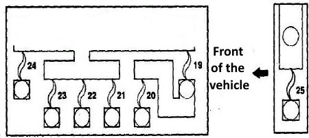
- 20 - Fuses (No. 4, 5) located in the engine compartment mounting block; fuses (No. 5, 6, 11, 12, 17, 18, 22, 23, 26) and fuse (No. 24) located in the passenger compartment mounting block 100A;
- 21 - Control unit (ABS or ASC) 30A;
- 22 - ABS malfunction relay; ASC control unit 50A;
- 23 - Fuses (No. 2, 3) and fuses (No. 10, 11, 12, 13, 14, 15, 16, 17, 18) located in the engine compartment mounting block 120A;
- 26 - Heater fuel line; coolant heater 50A.
Primary fuse box
Located on the left side of the engine compartment, next to the battery. Remove the protective cover for access.
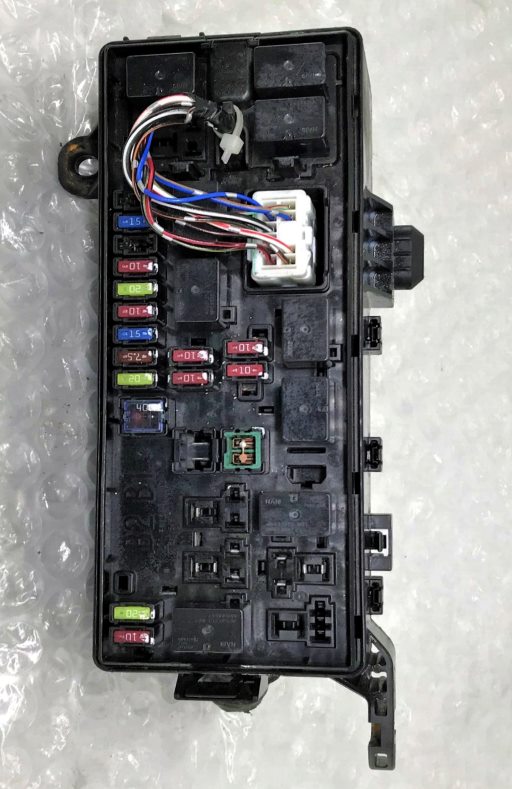
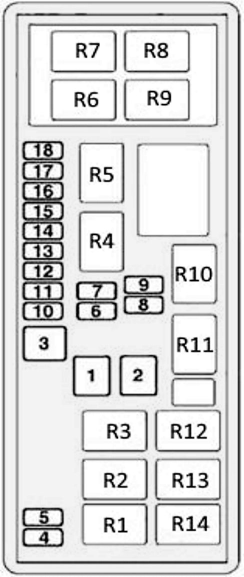
General view.
| Diagram | ||
|---|---|---|
|
||
| № | Description | Amps |
| 1 | Spare | - |
| 2 | Power window actuator system | 40 |
| 3 | ignition switch | 40 |
| 4 | Air conditioning compressor | 10 |
| 5 | Condenser Fan Motor | 20 |
| 6 | High beam headlight (left) | 10 |
| 7 | High beam headlight (right) | 10 |
| 8 | Dipped beam headlight (left) | 10 |
| 9 | Dipped beam headlight (right) | 10 |
| 10 | Engine control module | 20 |
| 11 | Alternator | 7.5 |
| 12 | Stop lights | 15 |
| 13 | Horn | 10 |
| 14 | automatic transmission control module | 20 |
| 15 | Warning lamp, alarm | 10 |
| 16 | L200 / Triton fuel pump fuse | 15 |
| 17 | Front fog lamps | 15 |
| 18 | Audio amplifier | 20 |
| R1 | Fog lamp relay | |
| R2 | Condenser fan motor relay | |
| R3 | Spare | |
| R4 | Starter | |
| R5 | Horn relay | |
| R6 | Fuel line heater | |
| R7 | Automatic transmission | |
| R8 | Main relay of the injection system | |
| R9 | Air conditioner compressor solenoid clutch | |
| R10 | dipped headlights | |
| R11 | High beam headlights | |
| R12 | Relay for electric drives glass lifters | |
| R13 | headlight washer relay | |
| R14 | Spare | |
Additional units
Depending on the year of manufacture and equipment level, additional units may be installed in the engine compartment of the Mitsubishi L200.
Unit near the right drain hole
The following relays can be installed: ABS pump motor relay and ABS fault relay
The unit next to the engine
It is installed mainly on diesel models. The relays responsible for heating the auxiliary electric heater are located here.
In the passenger compartment
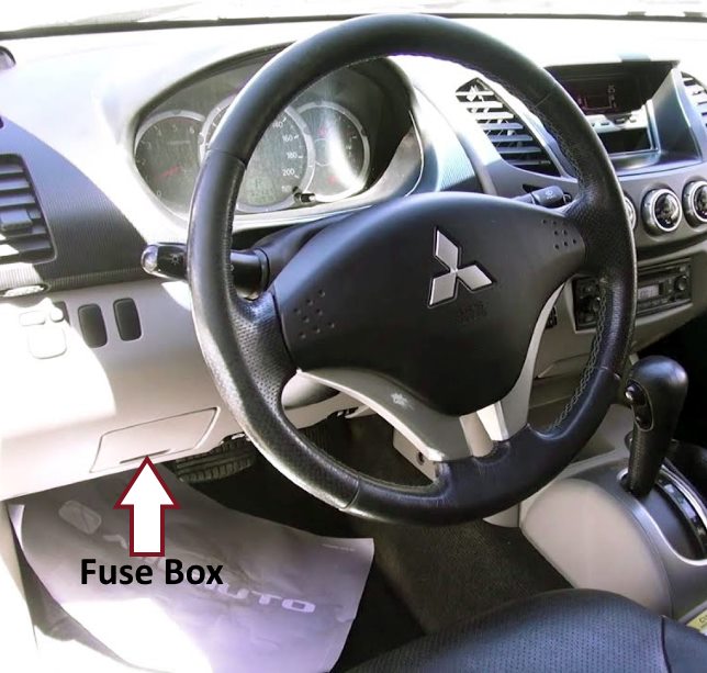
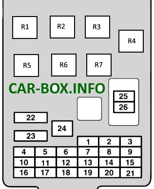
Located on the driver's side at the bottom of the dashboard, behind the plastic cover.
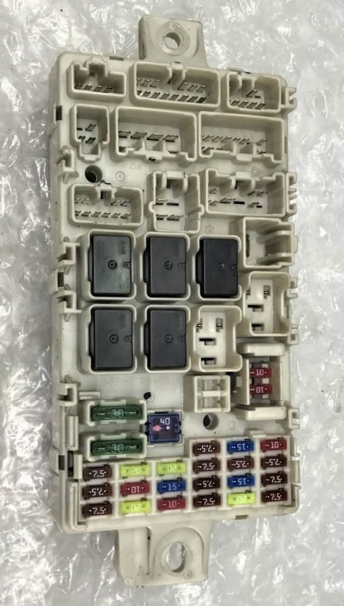
General view of the Mitsubishi L200 / Triton interior fuse box.
| Diagram | ||
|---|---|---|
|
||
| № | Description | Amps |
| R1 | Seat heating relay | |
| R2 | Power relay for auxiliary equipment outlets | |
| R3 | Rear fog lamp relay | |
| R4 | Fuel pump relay | |
| R5 | Fan relay | |
| R6 | Rear window defogger relay | |
| R7 | Spare | |
| 1 | Parking lights (left) | 7,5 |
| 2 | Mitsubishi L200 / Triton cigarette lighter fuse | 15 |
| 3 | Ignition coil | 10 |
| 4 | Starter | 7,5 |
| 5 | Sunroof | 20 |
| 6 | Socket for connection of additional equipment | 15 |
| 7 | Side lights (RH), A/C ECU, ASC OFF switch, blind spot warning switch, combination meter, drive mode switch, electric parking brake switch | 7,5 |
| 8 | Exterior mirrors | 7,5 |
| 9 | ECU and fuel pump relay | 7,5 |
| 10 | Control unit | 7,5 |
| 11 | Rear fog lamp | 10 |
| 12 | Central locking, diagnostic socket | 15 |
| 13 | A/C ECU, camera ECU, center light, column switch, combination instrument, door lamp, electric parking brake switch, front passenger compartment light, gateway control unit, key reminder switch (ILL), KOS and OSS ECU, light control sensor, luggage compartment lamp, multidisplay, radio/CD player and rear display | 10 |
| 14 | Rear window cleaner | 15 |
| 15 | Instrument panel, blind spot warning sensor, sunroof warning control unit, steering column switch | 7,5 |
| 16 | A/C compressor relay, A/C condenser fan relay, fan relay, heater controller, rear fan relay, rear cooler control panel, rear fan switch and rear window heater relay | 7,5 |
| 17 | Heated seat | 20 |
| 18 | Accessory Power, Heater Controller Assembly | 10 |
| 19 | Heated exterior mirrors | 7,5 |
| 20 | Wipers | 20 |
| 21 | Reverse lamps, automatic transmission control unit, ETACS control unit, multifunction display, radio/CD player, rear combination lamp, rearview mirror assembly and SRS control unit | 7,5 |
| 22 | Rear window heater, fuse #19, glass antenna choke coil and rear window heater | 30 |
| 23 | Heater fan motor relay | 30 |
| 24 | Power Seats | 40 |
| 25 | Audio system, auxiliary equipment connector relay, ETACS-ECU, multi-display, radio/CD player and rear display | 10 |
| 26 | Fuse No. 13 and ETACS-ECU | 15 |
