Nissan Primera was produced in 3 generations with sedan, station wagon and liftback bodies. The first generation - p10, was produced in 1990, 1991, 1992, 1993, 1994, 1995. The second is p11, in 1996, 1997, 1998, 1999, 2000. The third is p12, in 2001, 2002, 2003, 2004, 2005, 2006 and 2007. We will provide information with a description of the Nissan fuse and relay blocks of the example p12 (3rd generation), their photos, diagrams and the purpose of the elements. Separately, we note the cigarette lighter fuses.

In the passenger compartment
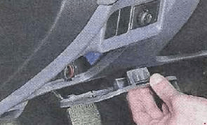
Fuse box located in the dashboard behind the protective cover, on the back of which the current diagram with the decoding of the elements will be applied.
| Diagram | |
|---|---|
|
|
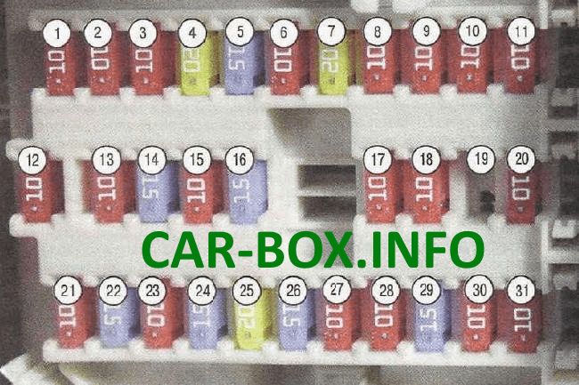
| №/Amp | Description |
| 1 - 10A | Audio system |
| 2 - 10A | Cruise control |
| 3 - 10A | Trunk lock electric drive |
| 4 - 20A | Trunk electrical outlet |
| 5 - 15A | Stop lights |
| 6 - 10A | Fog lights |
| 7 - 20A | Heated rear window (tailgate glass) |
| 8 - 10A | Heated front seats |
| 9 - 10A | Cruise control |
| 10 - 10A | Power supply for electronic devices |
| 11 - 10A | Automatic transmission control system |
| 12 - 10A | Power supply for electronic devices |
| 13 - 10A | Interior lampshades |
| 14 - 15A | Air blower motor |
| 15 - 10A | Air conditioning |
| 16 - 15A | Air blower motor |
| 17 - 10A | Engine management system |
| 18 - 10A | Supplemental Safe System (SRS) |
| 19 | Spare |
| 20 - 10A | Engine management system |
| 21 - 10A | Starter Solenoid Relay |
| 22 - 15A | Cigarette lighter |
| 23 - 10A | Electric drives for external rear-view mirrors |
| 24 - 15A | Center console electrical outlet |
| 25 - 20A | Windshield wiper |
| 26 - 15A | Windscreen and tailgate washers |
| 27 - 10A | Sensors |
| 28 - 10A | Tailgate glass cleaner |
| 29 - 15A | Fuel pump |
| 30 - 10A | Instrument cluster |
| 31 - 10A | Anti-lock braking system (ABS) |
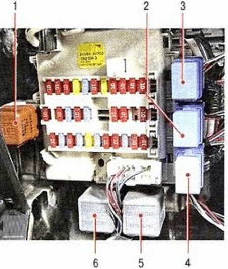
Relay on the front of the fuse box panel
- rear window heating relay;
- throttle motor relay;
- fog lamp relay;
- window regulator relay;
- relay breakers;
- relay breakers.
Relay on the back of the fuse box panel
- ignition relay;
- auxiliary equipment relay;
- air blower relay for ventilation, heating and air conditioning
In the engine compartment
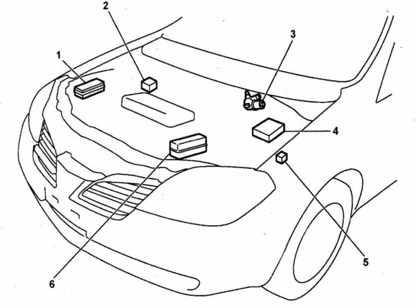
Location.
Fuse box
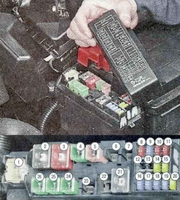
Diagram.
| № - Amp | Legend |
| 1 - 120A | 1st main fuse |
| 2 - 80A | Consumers with the ignition on |
| 3 - 50A | Anti-lock braking system pump motor |
| 4 - 40A | Ignition switch (lock) |
| 5 - 30A | Anti-lock braking system solenoid valves |
| 6 | Spare |
| 7 | Spare |
| 8 - 10A | parking lights |
| 9 - 15A | Audio system |
| 10 - 10A | Engine management system |
| 11 - 15A | Sound signal |
| 12 | Spare |
| 13 | Spare |
| 14 - 15A | Low beam (left headlight) |
| 15 - 15A | Low beam (right headlight) |
| 16 - 15A | Throttle actuator motor |
| 17 - 15A | High beam (left headlight) |
| 18 - 15A | High beam (right headlight) |
| 19 - 15A | Fog lights |
| 20 - 20A | Ignition coils |
| 21 - 80A | 2nd main fuse |
| 22 | Spare |
| 23 - 30A | Headlight washers |
| 24 - 40A | 2nd radiator fan motor |
| 25 - 40A | 1st radiator fan motor |
| 26 - 40A | Electric windows |
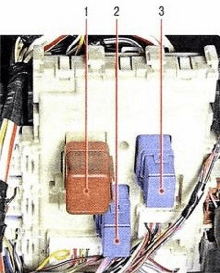
Relay box
![]()
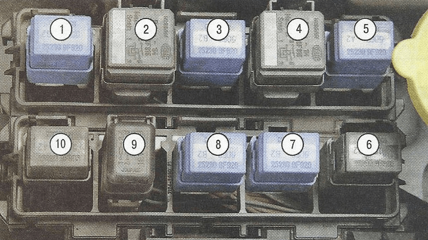
Diagram.
| № | Description |
| 1 | fog lamp relay; |
| 2 | radiator fan relay; |
| 3 | auxiliary equipment relay; |
| 4 | radiator fan relay; |
| 5 | air conditioning compressor electromagnetic clutch relay; |
| 6 | radiator fan relay; |
| 7 | relay for switching on modes "P" (parking) "N" (neutral) of an automatic transmission or variator; |
| 8 | daytime dipped beam relay; |
| 9 | sound signal relay; |
| 10 | radiator fan relay. |
