Most of the power circuits of the Japanese crossover electrical equipment are protected by fuses. Powerful current consumers are connected via relays. Protective elements are installed in mounting blocks located in the engine compartment and passenger compartment.
Considered diagrams Nissan X Trail T30 2001, 2002, 2003, 2004, 2005, 2006, 2007 release.
In the engine compartment
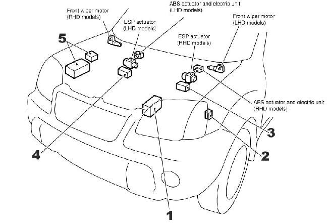
Location of components: 1. Fuse box; 2. Glow plug relay; 3. ESP relay box (right-hand drive); 4. ESP relay box (left-hand drive); 5. Relay box
Fuse box
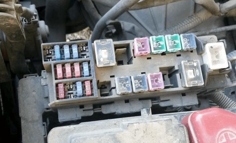
General view.
| Diagram | ||
|---|---|---|

|
||
| No. | Description | A |
| A | Alternator, engine compartment fuse box (fuses: # B to G, 39 to 43) | 100 / 120 * |
| B | Central locking, power windows, sunroof, power seats | 40 |
| C | Cooling fan | 40 |
| D | ||
| E | Headlight cleaners and washers | 30 |
| F | Glow plugs | 60 |
| G | Cabin fuse box | 80 |
| H | Air conditioning / heating system, passenger compartment fuse box (fuses: No. 18, 20, 23) | 80 |
| I | Vehicle Stability Program (ESP) | 50 |
| J | Egnition lock | 30 |
| K | ABS | 40 |
| L | ABS, ESP (30A with ESP, 40A without ESP) | 30 |
| M | No | 30 |
| 31 | Exterior lamps, headlamp cleaners and washers, warning devices and indicators | 10 |
| 32 | Audio system, navigation system, telephone | 15 |
| 33 | Engine control unit, anti-theft system | 1 |
| 34 | Generator, anti-theft system | 10 |
| 35 | Direction indicators | 15 |
| 36 | Rear fog lamp | 10 |
| 37 | ABS, four-wheel drive control system (4WD) | 10 |
| 38 | - | 10 |
| 39 | The engine control unit | 15 |
| 40 | Engine control unit, outside lamps | 15 |
| 41 | Outdoor lamps, fog lamps | 15 |
| 42 | Fog lights | 15 |
| 43 | Engine control unit, anti-theft system | 20 |
| * Gasoline engines | ||
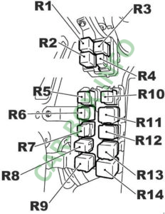
Relay box
#5 on the picture.
| Diagram | |
|---|---|
|
|
| No. | Description |
| R1 | lamps |
| R2 | daytime lighting systems, left (with daytime lighting system) |
| R3 | daytime lighting systems, right (with daytime lighting systems) |
| R4 | rear fog lamp |
| R5 | front fog lights |
| R6 | start inhibit ("P '' / '' N") |
| R7 | air conditioning |
| R8 | sound signal |
| R9 | cooling fan 1 |
| R10 | throttle control unit |
| R11 | cooling fan 3 |
| R12 | all-wheel drive system / Fuse box (vehicles with xenon) |
| R13 | cooling fan 2 |
| R14 | headlight washer |
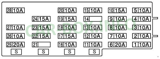
In the passenger compartment

The unit is located at the bottom of the dashboard, behind a plastic cover
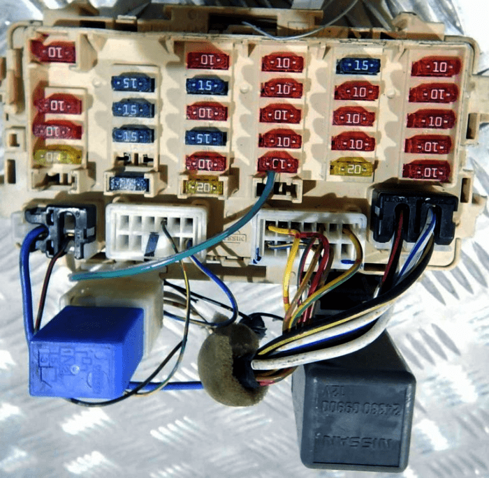
Photo - example.
| Diagram | ||
|---|---|---|
|
||
| No. | Decoding | A |
| 1 | Gasoline pump | 10 |
| 2 | Direction indicators | 10 |
| 3 | The engine control unit | 10 |
| 4 | Audio system, navigation system | 10 |
| 5 | Diagnostic connector, transmission control unit, central locking, anti-theft system, power windows, heated rear window, interior lamps, sunroof, warning devices and indicators, navigation system | 10 |
| 6 | Front glass wiper and washer | 20 |
| 7 | Engine control unit, daytime lighting control unit | 10 |
| 8 | ABS / ESP, four-wheel drive control system (4WD) | 10 |
| 9 | SRS | 10 |
| 10 | Fuel pump, engine control unit | 15 |
| 11 | Engine control unit, transmission control unit, ABS / ESP, four-wheel drive control system (4WD), SRS, instrument cluster, headlight washer / washer | 10 |
| 12 | Transmission control unit, reversing lights, navigation system | 10 |
| 13 | The engine control unit | 10 |
| 14 | Seat heating | 10 |
| 15 | Air conditioner / heater | 10 |
| 16 | Rear window wiper and washer | 10 |
| 17 | Cigarette lighter fuse x trail, accessory power connector | 15 |
| 18 | ten | |
| 19 | Air conditioner / heater | 15 |
| 20 | Power mirrors | 10 |
| 21 | Not used | - |
| 22 | Brake light switch, transmission control unit, ABS, four-wheel drive control system (4WD) | 15 |
| 23 | Cigarette lighter ext., Socket | 15 |
| 24 | Air conditioner / heater | 15 |
| 25 | Engine control unit, heated rear window | 20 |
| 26 | Interior lamps | 10 |
| 27 | Heated rear window | 10 |
| 28 | Engine control unit, transmission control unit, central locking, anti-theft system, heated rear window, interior lamps, sunroof, warning devices and indicators | 10 |
| S | Spare fuses | - |
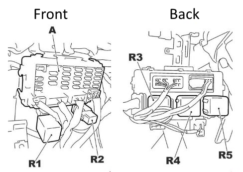
| Relay | ||
|
||
| R1 | PTC | |
| R2 | window lifters | |
| R3 | ignition | |
| R4 | heater fan | |
| R5 | Auxiliary relay | |
| A | Block in salon | |
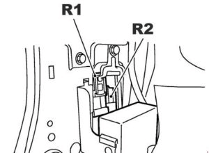
Also, several relays can be placed in the front pillar at the driver's feet (R1 - heated rear window / mirrors, R2 - Fuel pump relay)
