Meriva A was presented to the public at the Paris Motor Show in September 2002. In May 2003, it went on sale in Europe. The car was developed in the Brazilian center of GM on the basis of the third-generation Corsa. In this article we will understand in detail fuse box diagrams Opel / Vauxhall Meriva A (first generation) 2002, 2003, 2004, 2005, 2006, 2007, 2008, 2009, 2010 years of manufacture.
Here you will find the locations and photos of the mounting blocks. Also, we will separately mark the fuses responsible for the cigarette lighter and the fuel pump.
In the passenger compartment
There are two blocks here that are responsible for protecting the vehicle's electrical circuits.
Fuse box
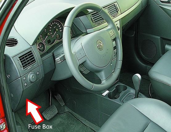
It is located under the dashboard cover.
To access it, you need to pull the lower part of the cover and remove it, overcoming the resistance of the latches.
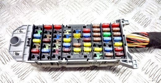
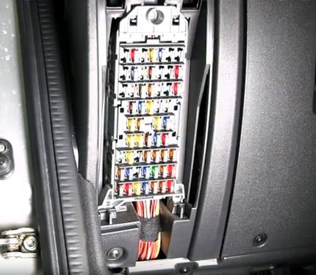
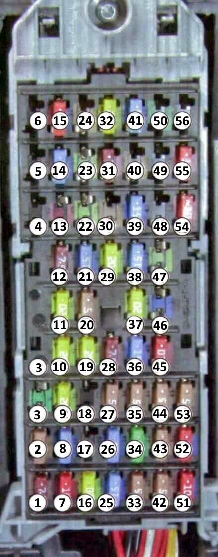
General view of the Opel / Vauxhall Meriva A interior fuse box.
| Diagram | ||
|---|---|---|
|
||
| No. | Description | Amps |
| 1 | Electrical control unit | 7.5 |
| 2 | Engine start interlock, emergency signaling, exterior lighting | 5 |
| 3 | headlight washer | 30 |
| 4 | Infotainment system, diesel engine management system | 20 |
| 5 | No | — |
| 6 | — | |
| 7 | Starter, diesel engine management system | 10 |
| 8 | Horn (beep) | 15 |
| 9 | Fuel injection system, Meriva A fuel pump fuse, additional heater | 20 |
| 10 | Direction indicators | 20 |
| 11 | Infotainment system, information display | 20 |
| 12 | Heated tailgate glass, heated exterior mirrors | 7.5 |
| 13 | Central locking, anti-theft alarm | 10 |
| 14 | Gasoline engine management system | 15 |
| Diesel engine management system | 7.5 | |
| 15 | Diesel engine management system (Z 17 DTH) | 10 |
| 16 | Electrical power outlet, Opel / Vauxhall Meriva A cigarette lighter fuse | 20 |
| 17 | Not used | ~ |
| 18 | Adaptive lighting system | 18 |
| 19 | central locking | 20 |
| 20 | Interior lighting | 5 |
| 21 | Window washers | 15 |
| 22 | Power windows for rear doors | 20 |
| 23 | Electric sunroof | 20 |
| 24 | Anti-theft alarm | 5 |
| 25 | Tailgate glass cleaner | 15 |
| 26 | Ignition system, electronic engine management system | 15 |
| 27 | Engine management system, Supplemental Restraint System (SRS), Dynamic Stability Program (ESP) | 5 |
| 28 | Air conditioner | 7.5 |
| 29 | Driver's door power window | 20 |
| 30 | Not used | |
| 31 | Engine management system | 7.5 |
| (same for Z 17 DTH engine) | 10 | |
| 32 | Front right door power window | 20 |
| 33 | Central electrical control unit, engine start interlock, signal lamps | 33 |
| 34 | Windscreen wipers | 30 |
| 35 | Interior lighting, electric rear view mirror, information display | 5 |
| 36 | Brake lights, anti-lock braking system (ABS), dynamic stability control (ESP) | 15 |
| 37 | Cigarette lighter fuse Meriva, additional heater | 20 |
| 38 | Heated driver's seat | 15 |
| 39 | Heated front passenger seat | 15 |
| 40 | Adaptive headlight, automatic headlight angle adjustment | 5 |
| 41 | Back-up lights | 15 |
| 42 | Engine cooling fan | 5 |
| 43 | Parking light on the left side | 5 |
| 44 | Parking light on the right side | 5 |
| 45 | Fog lights | 10 |
| 46 | Fog lights | 15 |
| 47 | Tow hitch, electrical outlet | 20 |
| 48 | Heating the diesel engine filter separator | thirty |
| 49 | No | — |
| 50 | Heating the diesel engine filter separator | thirty |
| 51 | Left headlight dipped beam lamp: | |
| gas discharge lamp | 15 | |
| halogen lamp | 10 | |
| 52 | Right headlight dipped beam lamp: | |
| gas discharge lamp | 15 | |
| halogen lamp | 10 | |
| 53 | Electric sunroof, power windows, radio | 5 |
| 54 | High beam lamp (left headlight) | 10 |
| 55 | High beam lamp (right headlight) | 10 |
| 56 | Not used | |
Relay box
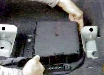
Located under the driver's seat. To access, release the cover latches and slide the cover forward.
| Diagram | |
|---|---|

|
|
| No. | Purpose |
| K1 | Locking the tailgate lock |
| K2 | Engine start blocking |
| K3 | Door locking |
| K4 | Driver's door lock |
| K5 | Unlocking the locks |
| K6 | Heated rear door window and heated exterior mirrors |
| K7 | Fog lights |
| K8 | Rear door glass cleaner |
| K9 | Rear electrical equipment |
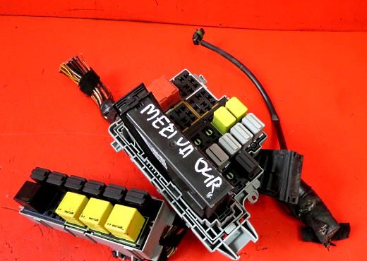
In the engine compartment
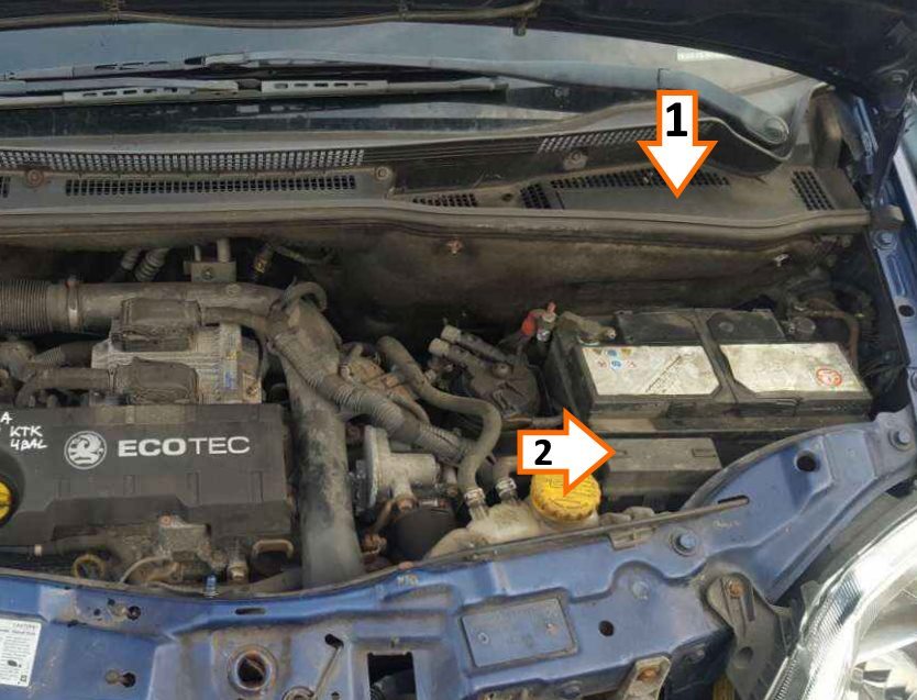
Component locations: #1 - relay box and main fuse panel, #2 - individual relays near the battery.
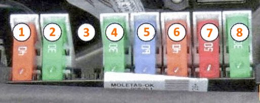
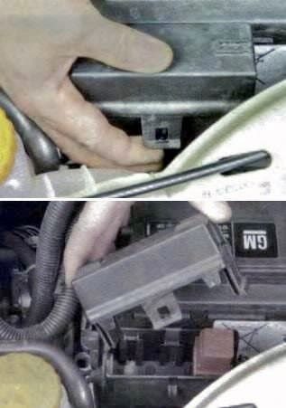
Main panel

Access Example.
| Diagram | ||
|---|---|---|
|
||
| No. | Decoding | Amps |
| 1 | Engine cooling fan | 40 |
| 2 | Starter | 30 |
| 3 | Engine cooling fan | 50 |
| 4 | Heated tailgate window | 30 |
| 5 | Easytronic automatic transmission | 60 |
| Glow plugs for diesel engines | 80 | |
| 6 | Anti-lock braking system | 40 |
| 7 | Electric power steering | 50 |
| 8 | Electric blower fan | 30 |
Relay box
It is located in the air inlet box.
General view.

Description.
K1. Ignition relay (ignition switch relay), pin "15";
K2. Starter switch on;
K2. Ignition relay (ignition switch relay), pin "15a";
K4. Fuel pump relay (fuel module);
K5. Engine ECU relay;
K6. Fog lights;
K7. Air conditioner compressor;
K8. Left side parking light switch relay;
K9. Right side parking light switch relay;
K10. High beam relay;
K11. Headlight dipped beam relay;
K12. Radiator fan relay;
K13. Not used;
K14. Reverse lights;
K15. Headlight washer pump relay;
K16. Right turn signals;
K17. Left turn signals;
K18. Windshield washer pump switch relay;
K19. Rear window washer pump switch relay;
K20. Windshield wiper intermittent operation relay;
K21. Windshield wiper constant mode relay;
K22. Antitheft system horn;
K23. Horn;
ECU. Central Electrical Control Unit.
Individual relays
On the battery shelf bracket there is a unit with an additional relay for the engine cooling fan. To access it, release the catch and slide the plastic cover.

Muy buena información y real eficaz gracias x su contenido