Most of the electrical circuits of a French minivan are protected by fuses. Powerful current consumers are connected via a relay. Protective elements are located in mounting blocks located in the passenger compartment and under the hood.

The information on the diagrams is relevant for Renault Kangoo (KC) 1st generation 1997, 1998, 1999, 2000, 2001, 2002, 2003, 2004, 2005, 2006, 2007 model year.
In the passenger compartment
The fuse mounting block is located on the left side of the passenger compartment, behind the protective cover. Just above it is the relay board.
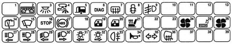
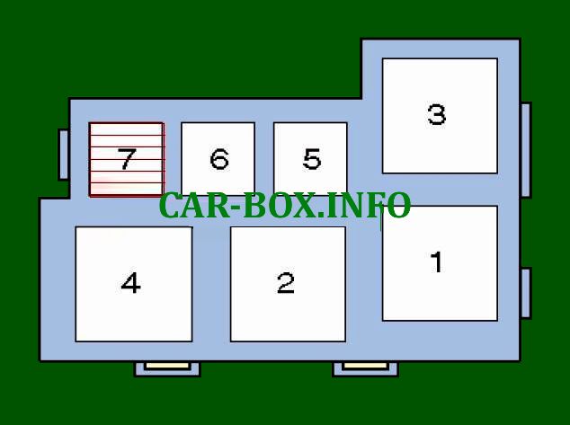
Fuse box
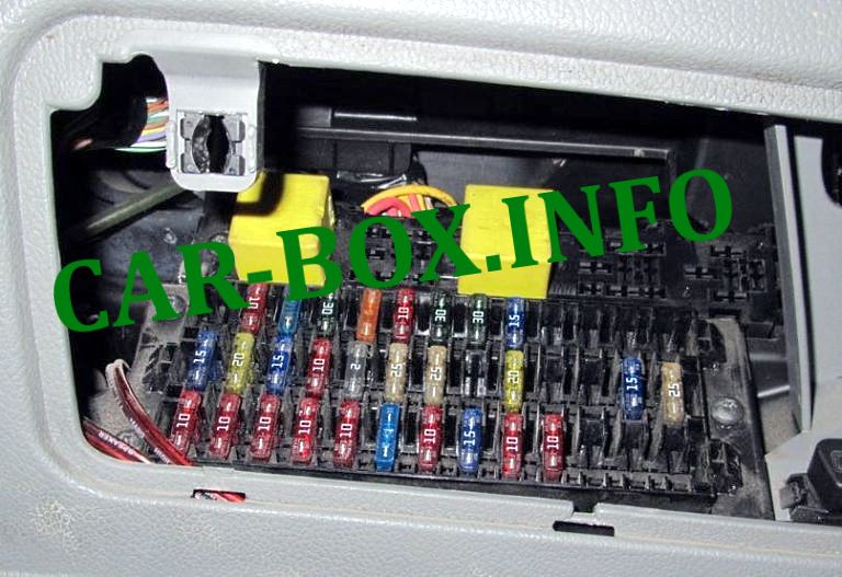
General form.
| Diagram | ||
|---|---|---|
|
||
| No. | Description | Amps |
| F1 | Empty | - |
| F2 | Audio / navigation system, clock, multifunction display, power door mirrors, telephone | 10 |
| F3 | Multifunctional control unit | 15 |
| F4 | Thermal fuse (F2 / F3) | 30 |
| F5 | Trailer electrical connector | 30 |
| F6 | Anti-theft system (some models), diagnostic connector (DLC), immobilizer, dashboard, multifunction control unit | 10 |
| F7 | Heated rear window | 30 |
| F8 | Multifunctional control unit | 3 |
| F9 | Fog lights | 15 |
| F10 | Empty | - |
| F11 | Empty | - |
| F12 | Empty | - |
| F13 | Empty | - |
| F14 | A / C compressor electromagnetic clutch relay (some models), rear window wiper / washer, reversing lights, windshield wiper / washer | 15 |
| F15 | Multifunctional control unit, windshield wiper / washer | 20 |
| F16 | Brake light switch (brake pedal position sensor), diagnostic connector (DLC), instrument cluster, electronic SRS control unit, telephone, automatic transmission selector lock relay | 15 |
| F17 | Anti-lock braking system (ABS) | 10 |
| F18 | Anti-theft control unit (some models), multifunction control unit | 2 |
| F19 | Power windows | 25 |
| F20 | 25 | |
| F21 | Seat heaters (some models) | 20 |
| F22 | Moonroof | 20 |
| F23 | Empty | - |
| F24 | Air conditioning electronic control unit (Left hand drive) | 15 |
| F25 |
|
15 |
| F26 | Air conditioning / heater control panel | 25 |
| F27 | LH headlight-high beam, instrument cluster | 10 |
| F28 | Right headlight - high beam | 10 |
| F29 | Left headlight - low beam, headlight range control | 10 |
| F30 | Right headlight - low beam, headlight range control, instrument cluster | 10 |
| F31 | Air conditioning / heater control panel, audio / navigation system, central locking, cigarette lighter, multifunction display, hazard warning lights, rear window defogger switch, instrument cluster, front left-hand side marker, license plate light, multifunction control unit, sunroof switch, burner lights | 10 |
| F32 | Power windows, seat heater, front right-hand side gauge, switch illumination, automatic transmission mode selection switch | 10 |
| F33 | (Instrument cluster, rear fog lights | 10 |
| F34 | Horn | 15 |
| F35 | Indicators / alarms (some models), multifunction control box | 10 |
| F36 | Heated door mirrors | 10 |
| F37 | Empty | - |
| F38 | Empty | - |
| F39 | Empty | - |
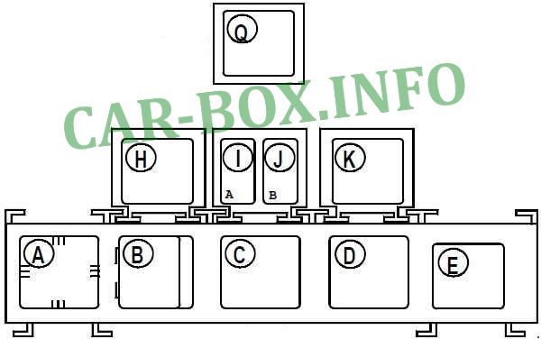
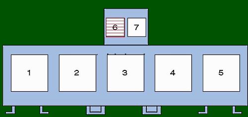
Relay box
Diagram.
| Type 1 | |
|
|
| No. | Description |
| A | Alarm buzzer about non-switched off outdoor lighting |
| B | Windshield Wiper Relay |
| C | Relay-interrupter for direction indicators and alarm |
| D | Rear wiper relay |
| E | Heated rear window relay |
| G | Relay "+" after ignition switch / "+" before ignition switch |
| H | Relay "+" after ignition switch / "+" before ignition switch |
| A / C compressor relay | |
| I | Fog lamp relay |
| Receiver for remote control of door locks | |
| J | Fuel level sensor relay (1061) (petrol / LPG systems) |
| K | Relay for electric door locks |
| L | Receiver for remote control of door locks |
| M | Relay for permanent low beam headlights |
| N | Daytime running light relay |
| O | Daytime running light main relay (vehicles with automatic transmission) |
| P | Daytime running light main relay (vehicles with manual gearbox) |
| Q | Receiver for remote control of door locks |
| Type 2 | |
|
|
| No. | Appointment |
| 1 | Heated rear window relay |
| 2 | Fog lamp relay |
| 3 | Relay for main ignition circuits |
| 4 | Daytime Lighting Relay - If Equipped |
| 5 | |
| 6 | |
| 7 | Empty |
In the engine compartment
The block is on the left side, near the counter. Digit 13 - fuse box, 14 - relay modules.
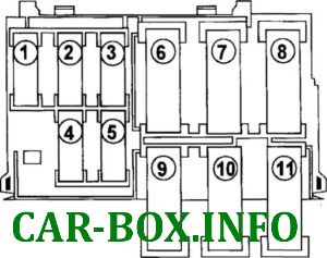
Fuse box
General form.
| Diagram | ||
|---|---|---|
|
||
| No. | Decoding | Amps |
| 1 | Engine management (injection system) | 30 |
| 2 | Cooling fan motor control (some models) | 30 |
| 3 | Engine management (D7F726) | 5 |
| 4 | Empty | - |
| 5 | Engine management | 15 |
| 6 | ECU for preheating system | 70 |
| 7 | Cooling fan motor control | 5 |
| 8 | Combination switch, daytime running lights (select models), fuse / relay box, instrument cluster (F4-F9), main ignition circuit relays | 60 |
| 9 | Anti-lock braking system ABS | 25 |
| 10 | 60 | |
| 11 | Central locking (some models), combination switch, fuse / relay box, instrument panel (F35) (some models), warning lamps (some models), ignition switch | 60 |
| 12 | A / C / heater fan control unit, A / C / heater fan motor | 40 |
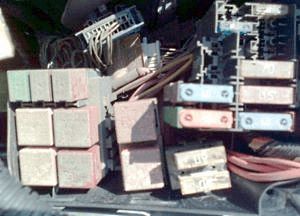
Relay box
| Type 1 | |

|
|
| No. | Appointment |
| 1 | Cooling fan motor relay 2 |
| 2 | Fuel module relay (fuel pump ) |
| 3 | Empty |
| 4 | A / C compressor electromagnetic clutch relay |
| 5 | Cooling fan motor relay 1 |
| 6 | Empty |
| 7 | Engine control relay |
| Type 2 | |
|
|
| No. | Description |
| 1 | Cooling fan motor relay 2 |
| 2 | Fuel pump relay |
| 3 | Cooling fan motor relay 2 (D4F712) |
| 4 | A / C compressor electromagnetic clutch relay |
| 5 | Cooling fan motor relay 1 |
| 6 | Starter relay (K7J 701, with automatic transmission) |
| 7 | Engine control relay |
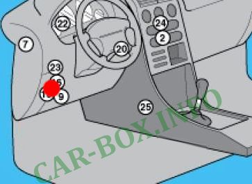
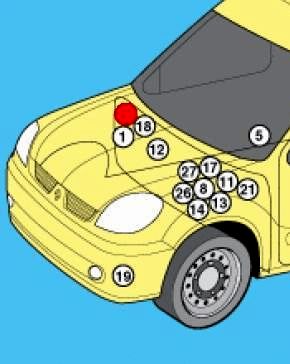
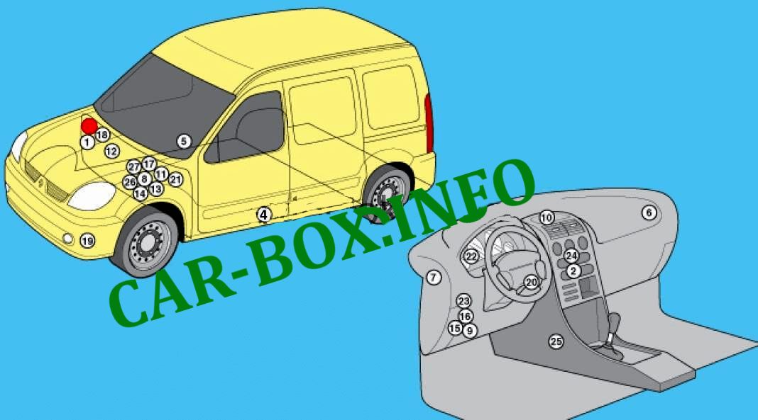
General arrangement
Location of the electrical equipment.
|
|
| No. | Component |
| 1 | ABS electronic control module |
| 2 | Air conditioning control module - center of the dashboard |
| 3 | Air conditioner / heater fan motor control module - intake system resonator |
| 4 | Side impact sensor, driver's side |
| 5 | Side impact sensor, passenger side |
| 6 | Theft Deterrent Control Module - If Equipped |
| 7 | Theft Deterrent Control Module (Alternate Position) - If Equipped |
| 8 | Accumulator battery |
| 9 | Diagnostic connector (DLC) |
| 10 | Multifunction Display - If Equipped |
| 11 | Electronic engine control unit - near the battery |
| 12 | Engine control unit (D4F, alternate position) - rear of the engine |
| 13 | Fuse / relay box, engine compartment 1 |
| 14 | Fuse / relay box, engine compartment 2 |
| 15 | Fuse / relay box, passenger compartment 1 |
| 16 | Fuse / relay box, passenger compartment 2 |
| 17 | Glow plug control unit - near battery |
| 18 | Heater blower motor resistor - intake system resonator |
| 19 | Horn |
| 20 | Ring antenna of the immobilizer - near the ignition switch |
| 21 | Inertial fuel cut-off switch |
| 22 | Instrument cluster control unit |
| 23 | Multifunctional control unit - functions: Anti-theft system (some models), audible warning / buzzer (some models), central locking, power windows (some models), diagnostics system, heated rear window, immobilizer, turn signals / hazard warning lamps, lighting lamps passenger compartment, instrument cluster, rear window wiper / washer, passive safety system (SRS), front / rear marker lamps, windshield wiper / washer |
| 24 | Navigation control unit (NIVAV3) - in the audio system unit |
| 25 | Electronic control module SRS |
| 26 | Electronic control module for automatic transmission (with automatic transmission) - near the battery |
| 27 | Vehicle speed sensor, without ABS - gearbox |
