Renault Twingo belongs to the small class cars. Started shipping to markets in 1993. The main part of the power supply circuits of the electrical equipment of the French hatchback is protected by fuses. Powerful current consumers are connected via relays. Protective elements are installed in the cabin and engine compartment mounting blocks.
Fuses diagrams of the Renault Twino (C06) 1st generation models 1998, 1999, 2000, 2001, 2002, 2003, 2004, 2005, 2006, 2007, 2008, 2009, 2010, 2011 and 2012 are considered.
In the engine compartment
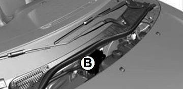
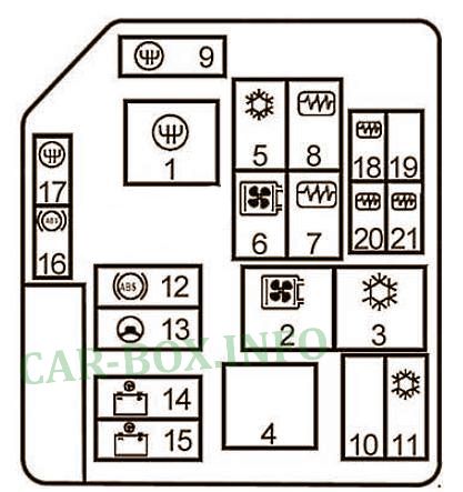
One of the fuse blocks is located in the engine compartment.
| Diagram | ||
|---|---|---|
|
||
| No. | Description | A |
| Circuit breakers | ||
| 9 | Sequential transmission | 30 |
| 10 | Empty | - |
| 11 | Air conditioning | 40 |
| 12 | Anti-lock braking system AB | 30 |
| 13 | Electric power steering | 30 |
| 14 | Fuse box in the passenger compartment | 60 |
| 15 | 60 | |
| 16 | Sequential transmission | 20 |
| 17 | Anti-lock braking system | 30 |
| 18 | Injection system | 10 |
| 19 | Empty | - |
| 20 | Injection system | 25 |
| 21 | Injection system | 50 |
| Relay | ||
| 1 | Sequential transmission | 50 |
| 2 | cooling fan unit (with air conditioning) | 50 |
| 3 | Low speed cooling fan (with air conditioning) | 25 |
| 4 | Empty | - |
| 5 | Air conditioning compressor | 25 |
| 6 | Fan unit (except air conditioner) | 25 |
| 7 | Injection blocking | 25 |
| 8 | Fuel pump relay | 25 |
In the passenger compartment
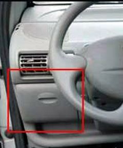
To access, pull the glove box towards you.
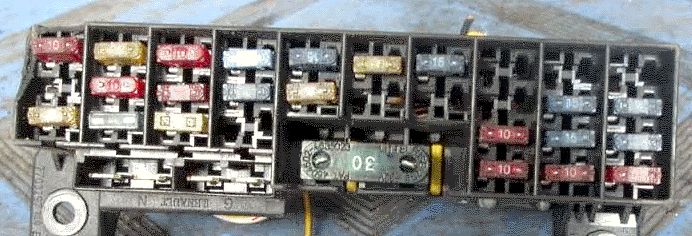
General view.
| Assignment of the fuses in the passenger compartment | ||
|---|---|---|

|
||
| No. | Description | A |
| 1 | Engine connection block | 20 |
| 2 | Rear window wiper, Reversing lights, Washer pump | 15 |
| 3 | Pretensioners, Airbag, Engine Immobilizer | 10 |
| 4 | Radio | 10 |
| 5 | Heated rear window | 20 |
| 6 | Injection system | 20 |
| 7 | Heating / air conditioning fan | 20 |
| 8 | Brake lights | 15 |
| 9 | Wiper | 15 |
| 10 | Rear fog lights | 10 |
| 11 | Antilock Braking System - ABS | 10 |
| 12 | Cigarette lighter fuse Twingo, Sunroof | 25 |
| 13 | Main headlamp high beam | 15 |
| 14 | High beam headlight, right | 15 |
| 15 | Electric power windows | 30 |
| 16 | Left dipped headlight | 15 |
| 17 | Right-hand dipped headlight | 15 |
| 18 | Left side lights | 10 |
| 19 | Right side lamps | 10 |
| 20 | Indicators, Rear fog lamp, UCH | 25 |
| 21 | Horn, Engine immobilizer | 10 |
| 22 | Interior lighting, Diagnostic socket | 10 |
| 23 | Electric power steering | 10 |
| 24 | Empty | - |
| 25 | Electric door lock, Electric door mirrors | 15 |
| 26 | Empty | - |
| 27 | Sequential reducer | 2 |
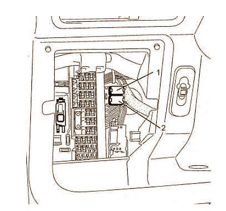
| The individual relay elements are located next to the main unit | ||
|
||
| 1 | Empty | |
| 2 | Front fog lights | |
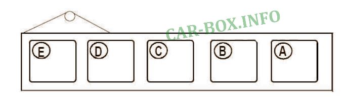
The optional relay board is located under the dashboard next to the pedals.
|
|
| No. | Decoding |
| A | Serial transmission |
| B | Empty |
| C | Sequential start of the transmission |
| D | Empty |
| E | Empty |
