Most of the power circuits of the electrical equipment of the Japanese minivan are protected by fuses. Powerful current consumers are connected via relays. Protective elements are installed in mounting blocks, which are located in the passenger compartment and in the engine compartment.

Fuse circuits are relevant for Toyota Avensis Verso cars (ACM20) 2001, 2002, 2003, 2004, 2005, 2006, 2007, 2008, 2009 release with gasoline engines 1AZ-FE (2.0 l) and 2AZ-FE (2.4 l).
In the passenger compartment
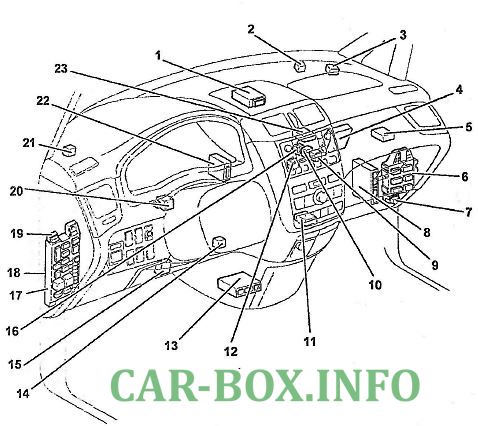
Location of components. 1 - electronic immobilizer control unit, 2 - "EX-HI" mode relay for the rear heater, 3 - rear heater relay, 4 - air conditioning amplifier (air conditioning with manual control), 5 - camera controller, 6 - central mounting block No. 1, 7 - fog lamp relay, 8 - electronic engine and automatic transmission control unit (models with automatic transmission) or electronic engine control unit (models with manual transmission), 9 - fan motor relay (M2), 10 - fan motor relay (M1), 11 - panel air conditioning and heater control assembly (manual air conditioning), 12 - antenna amplifier, 13 - SRS electronic control unit, 14 - transponder amplifier, 15 - auxiliary heater amplifier (models with 1AZ-FE engine), 16 - fan motor relay ( Hi),17 - fuse box under the dashboard , 18 - MULTIPLEX control unit, 19 - auxiliary consumer relay, 20 - direction indicator relay, 21 - fuel pump relay, 22 - anti-theft system electronic control unit, 23 - radio and multifunction display.
Fuse box
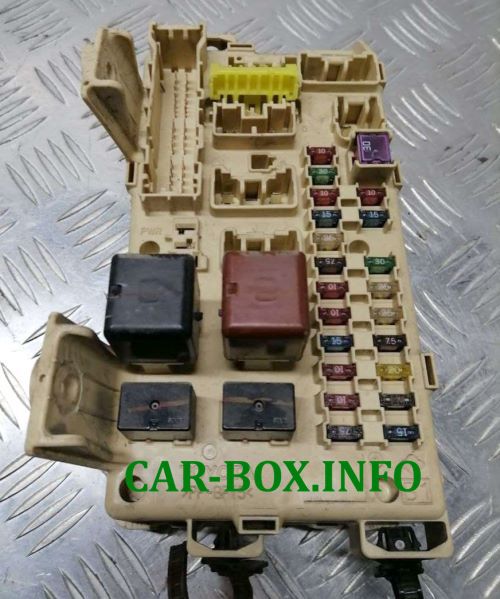
General view.
| Diagram | ||
|---|---|---|

|
||
| code | Description | A |
| ECU-ACC |
|
7.5 |
| ECU-IG |
|
7.5 |
| GAUGE |
|
7.5 |
| PANEL |
|
7.5 |
| HTR |
|
10 |
| IGN |
|
10 |
| MIR HTR | Heated rear window and heated mirrors | 10 |
| RR HTR | Rear heater | 10 |
| SEAT HTR | Seat heater | 10 |
| SRS-IG | SRS system | 10 |
| TAIL | Tail lamps | 10 |
| C / LTR | Cigarette lighter and socket for connecting additional equipment | 15 |
| FR FOG |
|
15 |
| PWR OUTLET |
Cigarette lighter and socket for connecting additional equipment | 15 |
| STOP |
|
15 |
| RR DEF | Heated rear window and heated mirrors | 20 |
| AM1 | Starting and ignition system (1AZ-FE) | 25 |
| DOOR |
|
25 |
| DOOR No. 2 |
Anti-theft system | 25 |
| WIPER |
|
25 |
| FR P / W | Power windows | 30 |
| PWR |
|
30 |
In the engine compartment
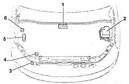
Location of components.
- relay box in the engine compartment #4,
- fuse box in the engine compartment #2
- headlight cleaner relay,
- pressure modulator and ABS electronic control unit,
- ABS relay box,
- relay glow plugs (1 CD-FTV).
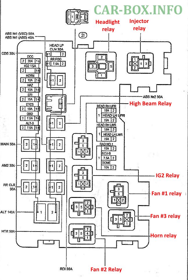
Fuse box
#2 on the picture.

General view.
| Diagram | ||
|---|---|---|
|
||
| code | Decoding | A |
| ALT-S | Charging system | 7.5 |
| ECU-B |
|
7.5 |
| OBD | Engine management system (models with 1AZ-FE engine) | 7.5 |
| Rr Fog | Rear fog lamp | 7.5 |
| DOME | Interior lamps | 10 |
| HORN | Sound signal | 10 |
| A / F | Engine management system (models with 1AZ-FE engine) | 15 |
| EFI |
|
15 |
| HAZ | Direction indicators and hazard warning lights (turn signal / flasher) | 15 |
| HEAD LH LWR |
|
15 |
| HEAD LH UPR | Headlamps | 15 |
| HEAD RH LWR |
|
15 |
| HEAD RH UPR |
|
15 |
| IG2 |
|
15 |
| RAD # 1 | Radio cassette | 15 |
| AM2 | Starting and ignition system (1AZ-FE) | 30 |
| CDS | Cooling fan and condenser fan drive (1AZ-FE) | 30 |
| FUEL HTR | Fuel heater | 30 |
| HEAD LP CLN | Headlight cleaner | 30 |
| RDI | Cooling fan and condenser fan drive (1AZ-FE) | 30 |
| RR CLR | Rear air conditioner | 30 |
| ABS No. 1 | Anti-lock braking system ABS | 40 |
| ABS No. 2 | 40 | |
| HTR | Front air conditioner | 50 |
| MAIN | Headlamps | 50 |
| ALT |
|
140 |
Relay box #2
Diagram.
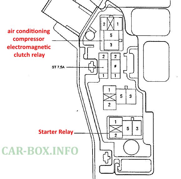
|
||
| ST |
|
7.5 A |
Relay box #4
Diagram.
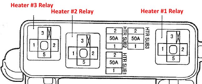
|
||
| HTR SUB1 | Additional heater (models with 1AZ-FE engine) | 50 A |
| HTR SUB2 | ||
| HTR SUB3 | ||
ABS relay box #5
Diagram.

|
Car body
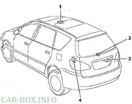
Location of components:
- sunroof control relay,
- rear air conditioner relay,
- rear door glass wiper relay,
- remote control receiver for central locking
