The Toyota Corolla Verso minivan for the European market was developed in Europe and produced in Turkey. Its design is based on the Corolla hatchback platform. The car has a very dynamic look and, with the ingenuity inherent in the Japanese, offers its original solution to the layout of a fairly compact, but at the same time roomy interior. In this material, we will analyze in detail the fuse circuits of the 2nd generation Toyota Corolla Verso (AR10 body): 2004, 2005, 2006, 2007, 2008, 2009 release.

Here you will find the locations and photos of the fuse blocks. Separately, we note the elements responsible for the cigarette lighter and fuel pump relay.
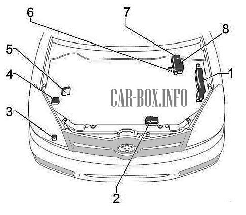
In the engine compartment
General layout of electronic components.
|
|
| No. | Component |
| 1 | Main fuse box |
| 2 | Relay box |
| 3 | Headlamp wiper relay |
| 4 | Exchange rate stability control module |
| 5 | Injector Control Module (EDU) |
| 6 | Glow plug relay |
| 7 | Additional fuse box (engines 1ZZ-FE, 3ZZ-FE ) |
| 8 | Additional fuse box (1CD-FTV engine ) |
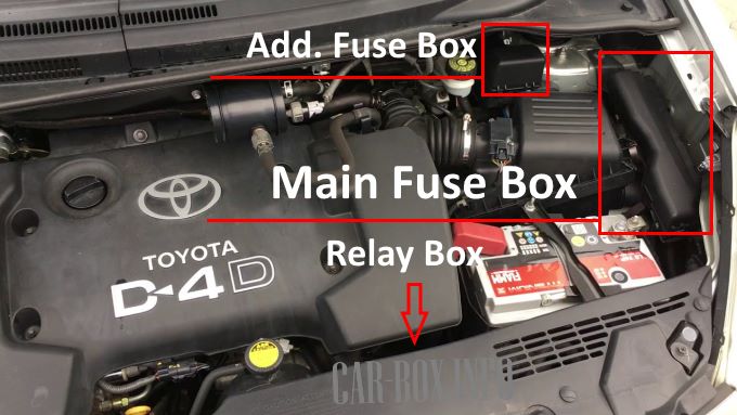
The main block is located on the left side of the engine compartment. Above it is an additional one. The relay box is located below the battery under the cladding.
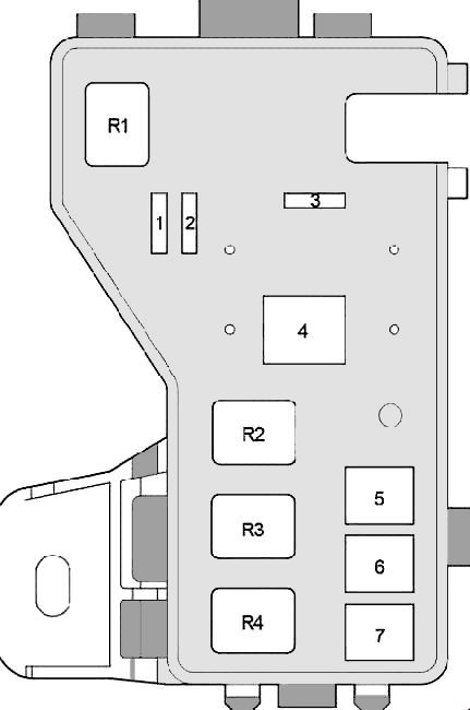
Main fuse box
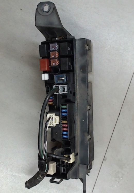
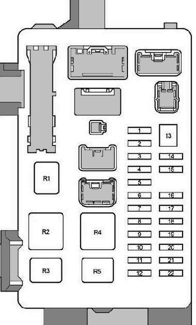
General view of the main unit.
| Diagram | ||
|---|---|---|
|
||
| No. | Description | A |
| 1 | Empty | - |
| 2 | ABS system, VSC | 25 |
| 3 | Empty | - |
| 4 | Empty | - |
| 5 | Empty | - |
| 6 | ALT-S - Charging system | 7.5 |
| 7 | DCC - Fuses: "ECU-B2", "DOME", "RAD2" | 30 |
| 8 | AM2 - Starting system, fuses: "ST", "IGN" | 30 |
| 9 | HAZARD - Direction indicators, hazard warning lights | 10 |
| 10 | F-HTR - 1CD – FTV: Fuel heating | 25 |
| 11 | HORN - Sound signal | 15 |
| 12 | EFI - sequential multiport fuel injection system, fuses: "EFI1", "EF22" | 30 |
| 13 | PWR HTR - engine 1CD – FTV : Auxiliary heater | 25 |
| 14 | RR DEF - Heated rear window | 30 |
| 15 | MAIN - Headlight cleaners, headlights, fuses: "H-LP HI LH", "H-LP HI RH", "H-LP LH", "H-LP RH" | 40 |
| 16 | AM1 # 1 - 1CD-FTV: fuses: "ACC", "CIG", "RAD NO.1", "ECU-B NO.1", "FL P / W", "FR P / W", "RL P / W "," RR P / W " | 50 |
| 17 | H / CLN - Headlight cleaners | 30 |
| 18 | HTR - Conditioner. heater | 40 |
| 19 | CDS - Cooling fan | 30 |
| 20 | RDI - engines 1CD-FTV, 1ZZ-FE, 3ZZ-FE: Cooling fan | 40 |
| RDI - engines 1AZ-FE, 1AZ-FSE: Cooling fan | 30 | |
| 21 | 1CD – FTV: ABS with VSC | 50 |
| 1CD – FTV: ABS without VSC | 40 | |
| 22 | IG2 - engines 1AZ-FSE, 1AZ-FE, 1ZZ-FE, 3ZZ-F E: Starting system, sequential multiport fuel injection system | 15 |
| 23 | THROTTLE - 1AZ-FSE, 1AZ-FE, 1ZZ-FE, 3ZZ-FE: Throttle ECU | 15 |
| ETCS - 1AZ-FSE, 1AZ-FE, 1ZZ-FE, 3ZZ-FE : Throttle ECU | 10 | |
| 24 | A / F - 1AZ-FSE, 1AZ-FE: Air-fuel ratio sensor | 20 |
| 25 | 1AZ-FSE, 1AZ-FE, 1ZZ-FE, 3ZZ-FE: - Empty | |
| 26 | ||
| 27 | EMPS - 1ZZ-FE, 3ZZ-FE: Power steering | 50 |
| Purpose of relay modules | ||
| R1 | Cooling fan 1CD – FTV (EFI MAIN) | |
| R2 | Cooling fan 1CD – FTV (EDU) | |
| R3 | FAN3 - Cooling fan 1CD – FTV | |
| R4 | FAN1 - Cooling fan | |
| R5 | FAN2 - Cooling fan 1AZ-FSE, 1AZ-FE, 1ZZ-FE, 3ZZ-FE | |
| R6 | 1AZ-FSE, 1AZ-FE, 1ZZ-FE, 3ZZ-FE: Empty | |
| R7 | FAN3 - 1AZ-FSE, 1AZ-FE, 1ZZ-FE, 3ZZ-FE: Cooling fan | |
| R8 | 1AZ-FSE, 1AZ-FE, 1ZZ-FE, 3ZZ-FE: Empty | |
| R9 | Engine 1ZZ-FE, 3ZZ-FE: Power steering EMPS | |
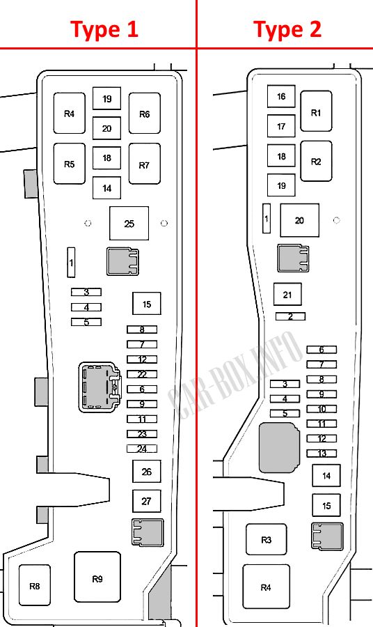
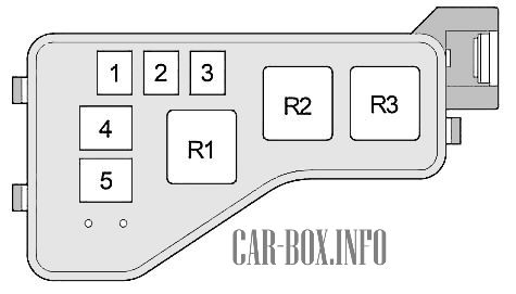
Additional fuse box
Diagram.
| Type 1 (engines 1ZZ-FE, 3ZZ-FE) | ||
|
||
| R1 | INJ - Injector (fuel injection system) | - |
| R2 | EFI - Engine control unit | - |
| R3 | IG2 - Ignition | - |
| R4 | A / F - Air-fuel ratio sensor | - |
| 1 | EFI1 - Multiport fuel injection system / sequential multiport fuel injection system | 10 |
| 2 | EFI2 - Emissions Control System | 7.5 |
| 3 | ABS, VSC | 25 |
| 4 | ALT - 1ZZ-FE, 3ZZ-FE: Fuses: "AM1 NO.1", "H-LP CLN", "ABS" (25A), "VSC" (25A), "ABS" (40A), "VSC" (50 A), "CDS", "RDI", "HTR", "RR DEF", "RR FOG", "FR FOG", "AM1", "DOOR", "STOP", "OBD2", "S / ROOF "," PWR SEAT "," P / POINT "," TAIL "," PANEL "," RR WIP "," ECU-IG "," WIP "," GAUGE2 "," GAUGE1 "," HTR ", "S-HTR" | 100 |
| ALT - 1AZ-FSE, 1AZ-FE: Fuses: "AM1 NO.1", "H-LP CLN", "ABS" (25A), "VSC" (25A), "ABS" (40A), "VSC" (50 A), "CDS", "RDI", "HTR", "RR DEF", "RR FOG", "FR FOG", "AM1", "DOOR", "STOP", "OBD2", "S / ROOF "," PWR SEAT "," P / POINT "," TAIL "," PANEL "," RR WIP "," ECU-IG "," WIP "," GAUGE2 "," GAUGE1 "," HTR ", "S-HTR" | 120 | |
| 5 | ABS with VSC | 50 |
| ABS system without VSC | 40 | |
| 6 | 50A AM1 NO.1 - Fuses: "PWR SEAT", "FR DIC", "FUEL OPN", "ECU-B 1", P-RR P / W "," P-FR P / W "," D- RR P / W "," D-FR P / W " | 50 |
| 7 | 30A H-LP CLN - Headlight cleaners | 30 |
| Type 2 (1CD-FTV engine) | ||
|
||
| R1 | Empty | - |
| R2 | Auxiliary heater HTR2 | - |
| R3 | Auxiliary heater HTR1 | - |
| 1 | Empty | - |
| 2 | Auxiliary heater HTR2 | 50 |
| 3 | Auxiliary heater HTR1 | 50 |
| 4 | GLOW - Glow plugs | 80 |
| 5 | ALT - Relay: "IG1", "TAIL", "SEAT HTR" , fuses: "H-LP CLN", "AM1 NO.1", "RDI", "CDS", "VSC" (50A), "VSC "(25A)," ABS "(40A)," ABS "(25A)," H / CLN "," RR DEF "," GLOW "," HTR NO1 "," HTR NO2 "," RFGHTR "," AM1 NO.2 "," RR FOG "," S / ROOF "," STOP "," P / POINT "," FR FOG "," OBD2 "," DOOR " | 140 |
Relay box
Diagram.

|
||
| No. | Description | A |
| R1 | HORN - Sound signal | - |
| R2 | F-HTR - Fuel heating | - |
| R3 | H-LP - headlamp relay | - |
| R4 | DIM - Dimmer | - |
| R5 | FAN2 - Cooling fan relay | - |
| 1 | H-LP HI LH - Left headlamp (high beam) | 10 |
| 2 | H-LP HI RH - Right headlamp (high beam), instrument cluster | 10 |
| 3 | H-LP LH - Left headlamp (low beam) | 15 |
| 4 | H-LP RH - Right headlamp (low beam) | 15 |
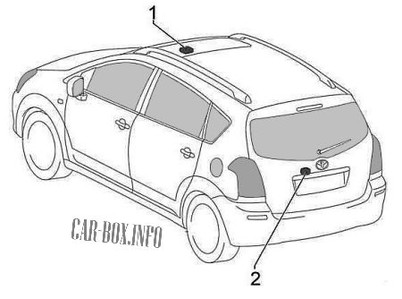
In the passenger compartment
General layout of electronic components.

Left-hand drive models. |
|
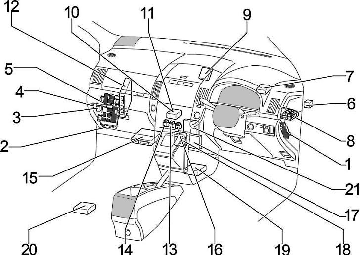
Right-hand drive models. |
|
| No. | Component |
| 1 | Additional fuse box |
| 2 | Body ECM |
| 3 | Heated rear window relay |
| 4 | Toyota Corolla Verso Fuel Pump Relay (Circuit Opening) |
| 5 | Main fuse box |
| 6 | Turn signal relay (alarm) |
| 7 | Central locking receiver |
| 8 | Distribution block |
| 9 | Key transponder control module |
| 10 | Air conditioning control module (automatic air conditioning) |
| 11 | Air conditioner amplifier |
| 12 | Engine control module |
| 13 | Relay box # 2 |
| 14 | Relay box # 3 |
| 15 | Transmission control module |
| 16 | Relay box # 1 |
| 17 | Wiper relay |
| 18 | Parking Sensor Management Module (Clearance Sonar) |
| 19 | Central airbag unit |
| 20 | TV camera control module |
| 21 | Ignition control module |
Main fuse box

For left-hand drive cars, the main fuse block is located on the driver's side, at the bottom of the dashboard behind the protective cover, next to it there is an additional one . For right-hand drive models, the main unit is located on the passenger side behind the glove compartment, and the additional unit on the driver's side behind the protective cover.
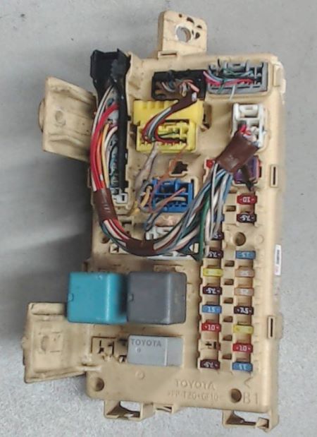
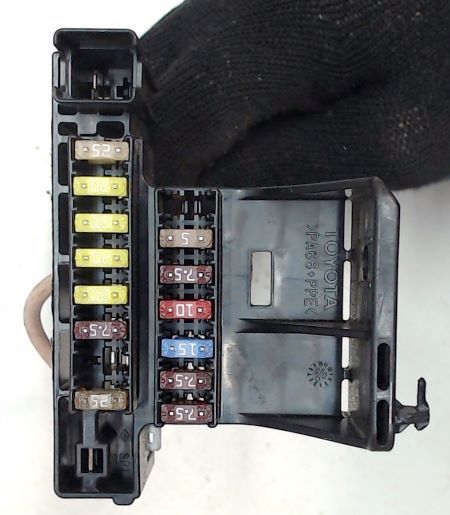
Photo is an example of the main block.
| Diagram | ||
|---|---|---|
|
||
| No. | Decoding | A |
| 1 | IGN - SRS airbags, instrument cluster, starting system, multiport fuel injection system / sequential multiport fuel injection system | 10 |
| 2 | Sunroof | 20 |
| 3 | RR FOG - Rear fog lamps | 7.5 |
| 4 | FR FOG - Front fog lamps, fog light indicator | 15 |
| 5 | AM1 - Starting system, fuses : "CIG", "RAD1" | 25 |
| 6 | Instrument panel illumination, instrument cluster illumination, automatic transmission control unit, glove box illumination, armrest compartment illumination, headlamp cleaners, front fog lamps, parking assistance, multi - information display (PANEL) | 7.5 |
| 7 | RR WIP - Rear wiper and washer | 20 |
| 8 | Reversing lamps, headlight range control, turn signal lamps, hazard warning lamps (GAUGE2) | 7.5 |
| 9 | CIG - Cigarette lighter fuse Toyota Corolla Verso | 15 |
| 10 | HTR - Heated seats, air conditioning | 10 |
| 11 | Empty | - |
| 12 | RAD1 - Audio system, information display, power mirrors, instrument cluster, socket | 7.5 |
| 13 | PWR SEAT - Power Seats | 30 |
| 14 | TAIL - Tail lamps, license plate lamps, luggage compartment lamps, automatic lighting system, front fog lamps, rear fog lamps, instrument cluster | 10 |
| 15 | OBD2 diagnostic connector | 7.5 |
| 16 | P / POINT - 12V power outlet | 15 |
| 17 | DOOR - Central locking | 25 |
| 18 | WIP - Front wiper and washer, headlight cleaners | 25 |
| 19 | ECU-IG - Cooling Fan, Charging System, Power Steering, ABS, VSC | 7.5 |
| 20 | Heated seats (S-HTR) | 20 |
| 21 | Light switch, multi - information display, integrated relay, instrument cluster, gear selector lock, automatic transmission control unit, rear view mirror, wiper, parking brake (GAUGE1) | 10 |
| 22 | Stop lamps, gear selector lock, auxiliary brake light, sequential multiport fuel injection (STOP) | 15 |
| R1 | Spare | - |
| R2 | HTR - Heater | - |
| R3 | SEAT HTR - Heated seats | - |
| R4 | IG1 - Ignition | - |
| R5 | TAIL - Tail lamp relay | - |
Additional fuse box
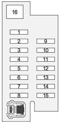
General view.
| Diagram | ||
|---|---|---|
|
||
| No. | Description | A |
| 1 | ACC - Start Button, Immobilizer, Steering Lock (Left Hand Drive) | 25 |
| 2 | Power Window - P-RR P / W | 20 |
| 3 | Power Window - P-FR P / W | 20 |
| 4 | Power Window - D-RR P / W | 20 |
| 5 | Power Window - D-FR P / W | 20 |
| 6 | ECU-B 1 - Gearbox | 7.5 |
| 7 | FUEL OPN - Fuel filler flap | 10 |
| 8 | FR DIC - Heated area of windscreen wiper blades, fuse: "MIR HTR" | 20 |
| 9 | А / С - Air conditioner (mechanical air conditioner), auxiliary heater | 10 |
| 10 | DEF I / UP - Air conditioner | 7.5 |
| 11 | ST - information display, sequential multiport fuel injection system, starting system | 7.5 |
| 12 | MIR HTR - Heated mirrors | 10 |
| 13 | RAD NO.2 - Audio system, multimedia display | 15 |
| 14 | DOME - Interior lighting, personal lighting, door lighting, luggage compartment lighting, individual mirror lighting, footwell lighting | 7.5 |
| 15 | ECU-B 2 - Air conditioner, wireless control system | 7.5 |
| 16 | PWR SEAT - Power Seats | 30 |
Relay blocks
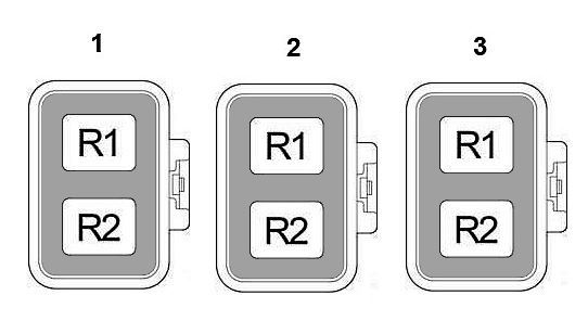
Description.
|
|
| Block #1 | |
| R1 | Auxiliary (ACC) |
| R2 | ST - starter relay |
| Block #2 | |
| R1 | 12V power outlet |
| R2 | IG2 - Ignition |
| Block #3 | |
| R1 | Front fog lamps |
| R2 | Rear fog lamps |
Car body electrical equipment
Components:
- Sunroof control unit,
- Rear wiper relay
