Volkswagen Beetle A5 is also known as the Beetle. Another car has the same nickname - Volkswagen New Beetle. However, these are different models. In our material you can familiarize yourself with the description of fuses and relays Volkswagen Beetle with photos and block diagrams for cars produced in 2011, 2012, 2013, 2014, 2015, 2016, 2017, 2018, 2019.
The number of fuses in the blocks and the purpose may differ and depends on the year of manufacture and configuration of the Volkswagen Beatle.
In the engine compartment

Fuse box located next to the battery, under the protective cover.
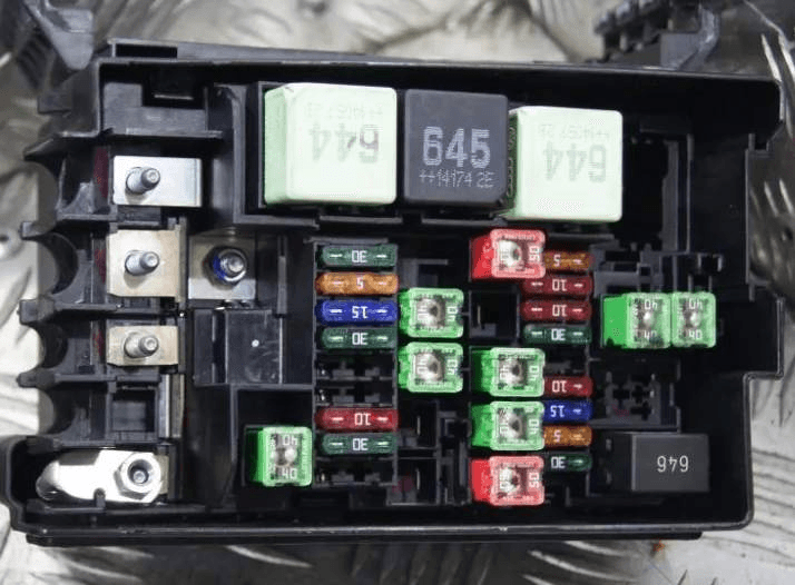
The photo
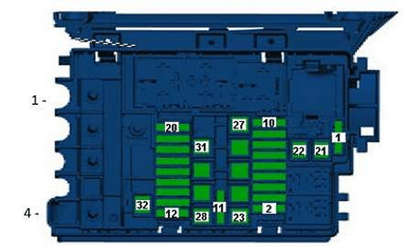
| Diagram | |
|---|---|
|
|
| № | Description |
| 1 | Spare |
| 2 | 20 / 30A - Engine control unit |
| 3 | 5A - Radiator fan control unit |
| 4 | 15A - Lambda - probe |
| 5 | 10A - Lambda probe, Electric fuel pump relay, Heating resistance relay, Solenoid valve for boost pressure limitation, Heating resistor for crankcase ventilation, Valve 1, variable valve timing, Turbocharger bypass valve, Intake manifold flap valve, Recirculation radiator changeover valve, Diagnostic fuel pump |
| 6 | 10A - Fuel pump relay, Secondary air pump relay, |
| 7 | Engine power supply relay , Turbocharging pressure limiting solenoid valve, Adsorber solenoid valve, Intake manifold flap valve, Oil pressure control valve |
| 8 | 20 / 30A - Throttle body, Ignition coil 1 with output stage, Ignition coil 2 with output stage, Ignition coil, Fuel pressure regulator, Fuel metering valve. |
| 9 | 10A - Air mass meter, Fuel pump relay, Solenoid valve for boost pressure limitation, Solenoid valve 1 of the adsorber, Valve 1 of the camshaft adjuster, Valve 2 of the exhaust gas recirculation system, Bypass valve of the turbocharger, Electromagnetic clutch of the drive blower, Oil pressure control valve, Coolant control valve, Coolant circulation pump 2 |
| 10 | 10A - Relay for pumping coolant after off. Engine control unit, Glow plug control unit, Low heating power relay, High heating power relay, Relay for additional coolant pump, Power supply relay for engine electronics, Fuel pressure regulator, Coolant circulation pump 2 |
| 11 | 5A - Clutch pedal position sensor, Brake light switch |
| 12 | Reserve |
| 13 | Reserve |
| 14 | 30A - Voltage stabilizer, Control unit with display for radio navigation system, Control unit for navigation system, |
| 15 | Head unit |
| 16 | 10A - Motronic supply relay, Terminal 30 supply relay, Engine control unit |
| 17 | 10A - Alarm siren relay |
| 18 | 40A - Amplifier |
| 19 | 15 / 30A - Gearbox mechatronic unit DSG |
| 20 | 15A - DSG gearbox mechatronic unit |
| 21 | 5A - Onboard power supply control unit (battery) |
| 22 | 30A - Onboard supply control unit |
| 23 | 40 / 50A - Heating element for additional air heater, Secondary air pump motor |
| 24 | 40A - Heating element of additional air heater |
| 25 | Spare |
| 26 | 40 / 50A - Terminal 75 power supply relay 1 |
| 27 | 40A - Terminal 15 power supply relay |
| 28 | 50A - Glow plug control unit |
| 29 | 50A - Radiator fan control unit |
| 30 | 20 / 30A - Fuel pump relay, Engine electronic components power relay |
| 31 | Spare |
| 32 | 40A - ABS control unit |
| 33 | |
| 34 | 40A - Heating element of additional air heater, Secondary air pump motor |
| High power fuse links | |
| 1 | 200A - Generator |
| 2 | Spare |
| 3 | 80A - Power steering control unit |
| 4 | 80A - Fuses |
| There are also separate elements of the relay: glow plugs, cooling fan, etc. | |
In the passenger compartment
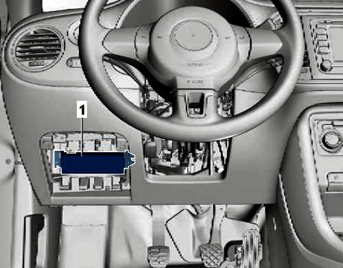
Fuse box located under the dashboard on the driver's side behind the protective cover.
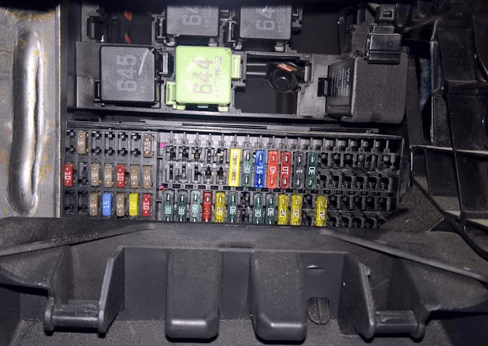
The photo.
Please note that the rest of the relays are located right there.
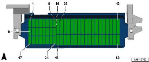
| Diagram | |
|---|---|
|
|
| № | Description |
| 1 | 5A - BU 2 control of blind spots |
| 2 | 10A - Control unit of the emergency call module and communication unit |
| 3 | 5A - BU of a combination of devices |
| 4 | 5A - Receiving - transmitting telephone device |
| 5 | 10A - control unit of the instrument cluster, onboard supply control unit, left fog lamp lamp |
| 6 | 10A - Button for unlocking in the tailgate handle, Rearview camera |
| 7 | 5A - Dimmer for switches and instrument cluster illumination, License plate illumination |
| 8 | 10A- Windscreen washer pump |
| 9 | 5A - Airbag control unit, Front passenger airbag deactivation warning lamp, Seat occupied recognition control unit |
| 10 | 15A - Intermittent wiper switch |
| 11 | 5A - Lighting switch |
| 12 | Spare |
| 13 | 5A - Start-stop mode button, Folding mirror switch, Tire pressure indicator button, Reversing light switch, High pressure sensor, Air pollution sensor, Heater control unit, Parking aid control unit, Vehicle tracking system control unit, Electrochromic interior mirror , Washer jet heating resistor |
| 14 | 10A - Cruise control switch, Tiptronic switch, Oil level and oil temperature sensor, Additional instruments, ABS control unit, instrument cluster control unit, Power steering control unit, Steering column control unit, Voltage stabilizer, Data bus diagnostic interface, Fuel pump control unit , Selector lever sensor control unit, Engine control unit, Crankcase ventilation heating resistor |
| 15 | 5A - Dimmer for switches and instrument cluster illumination, Air flow meter, Vibration suppression system control unit, Headlight range control actuator, Connector, 16-pin, diagnostic connector. |
| 16 | 5A - Engine control unit |
| 17 | 10A - Interior monitoring system sensor, Vehicle tilt sensor, Alarm siren |
| 18 | 15A - Lamp of the left headlight dipped beam |
| 19 | 15A - Right-hand dipped beam lamp |
| 20 | 10A - Tiptronic switch, Heater control unit, Automatic transmission control unit, Climatronic control unit, Air conditioning control unit, Selector lever sensor control unit, Ignition key extraction lock solenoid |
| 21 | 15A - Onboard supply control unit |
| 22 | 5A - Ignition and starter switch, Vehicle tracking control unit |
| 23 | 10A - Rain and light sensor, Onboard power supply control unit, Telephone transceiver, Control unit for emergency call module and communication unit, Connector, 16-pin -T16-, diagnostic connector, Additional devices |
| 24 | 10A - Onboard power supply control unit, Access and start authorization control unit, El. steering column lock, data bus diagnostic interface |
| 25 | 10 / 25A Automatic transmission control unit, Multi-function switch, DSG mechatronic unit |
| 26 | 30A - Vacuum pump of the brake system |
| 27 | Spare |
| 28 | 25A - Terminal 75 power supply relay 1 |
| 29 | 5A - Onboard supply control unit |
| 30 | 20A - Blocking diode, Cigarette lighter , 12V socket. |
| 31 | 30A - Light switch |
| 32 | 15A - Fog lamps switch |
| 33 | 40A - Heater control unit, air conditioning control unit |
| 34 | 10 / 15A - control unit of the instrument cluster, control unit for onboard power supply, lamp of the left high beam headlight, lamp of the right high beam headlight, headlights |
| 35 | 10A - Steering column control unit |
| 36 | 30A - Onboard supply control unit |
| 37 | 5A - Lamp of the left module of daytime lighting |
| 38 | 5A - Lamp of the right daytime running light module |
| 39 | 30A - Relay for manual dipped beam and light signal (high beam) |
| 40 | Spare |
| 41 | Spare |
| 42 | Spare |
| 43 | 30A - Front passenger door control unit |
| 44 | 30A - Onboard supply control unit |
| 45 | 30A - Driver's door control unit |
| 46 | Spare |
| 47 | 20A - Fuel pump relay |
| 48 | 30A - Onboard supply control unit |
| 49 | 40A - Supply fan control unit |
| 50 | 30A - Front seat heating control unit |
| 51 | 30A - Sliding sunroof control unit |
| 52 | 20A - Onboard supply control unit |
| 53 | |
| 54 | 25A - Automatic transmission control unit |
| 55 | 20A - Light switch, Low beam and light switch (including high beam) |
| 56 | 20A - Onboard supply control unit |
| 57 | 25A - Control unit with display radio navigation system, Head unit |
| 58 | 10A - Reducing agent dosing system relay |
| 59 | Spare |
| 60 | Spare |

I am looking for the relay that controls the turn signals and the hazard lights, any information to be shared regarding these?