The Volkswagen Crafter is still available in various body styles: minibus, light truck and cargo-passenger van. Years of production of the 1st generation: 2006, 2007, 2008, 2009, 2010, 2011, 2012, 2013, 2014, 2015, 2016. During this period, the car was restyled. Since 2017, the second generation of the updated Crafter has been delivered to the markets. In this article you will find a description of Crafter fuse blocks and relays, diagrams and photos of the blocks, as well as their location. Let's highlight the fuse responsible for the cigarette lighter.

Depending on your vehicle equipment level (Standard, HighLine, etc.) and the year of manufacture, different designs of fuse boxes and relays are possible.
General arrangement

The following blocks are provided in Crafter:
- Power supply fuse, cl. 30 -S190-
- Battery fuse holder A -SA-
- Fuse holder B, left pillar -SB-
- Left-hand fuse and relay box C -SC-
- Fuse and relay holder under driver's seat -SD-
- Additional fuses under the driver's seat
Power supply fuse, cl. 30
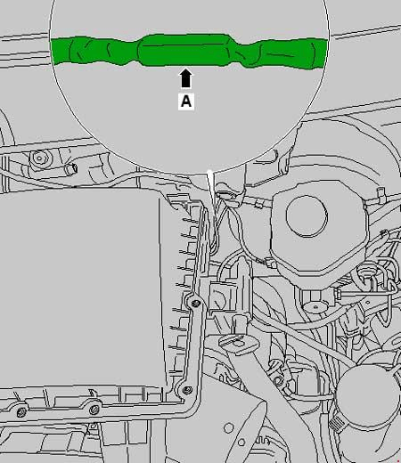
Main power supply fuse, cl. 30, located in the wiring harness between the alternator and starter
Battery fuse box
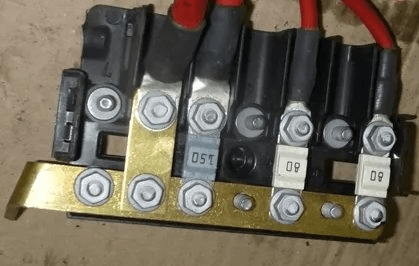
It consists of high power fuse-links.
| Diagram | |
|---|---|
|
|
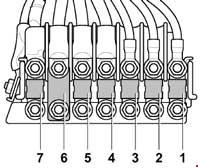
| № | Amps / Description |
| 1 | 80A Glow plug control unit |
| 2 | 40/60 / 80A Radiator fan control unit, Radiator fan |
| 3 | 80A Onboard supply control unit, Engine electronics power supply relay Fuse box C |
| 4 | 150A Second battery, Bodywork main fuse Fuse box D |
| 5 | 150A Terminal 15 voltage supply relay, Horn relay, Onboard supply control unit Fuse box B or Fuse box C |
| 6 | Relay for unloading cl. 15, Power supply relay 1 Heated windscreen fuse Fuse box D |
| 7 | 150A Heating element of additional air heater |
Left side blocks
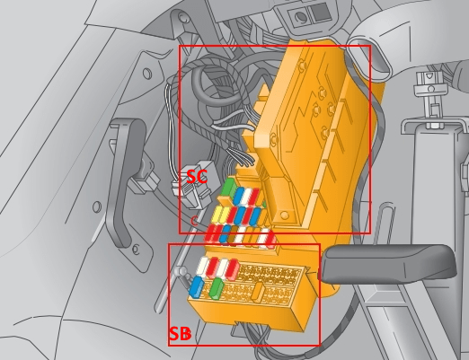
It is located on the left in the footwell under the dashboard and consists of 2 blocks: Fuse box B and Fuse and relay box C.
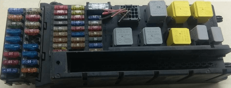
Photo example.
Fuse box -SB-
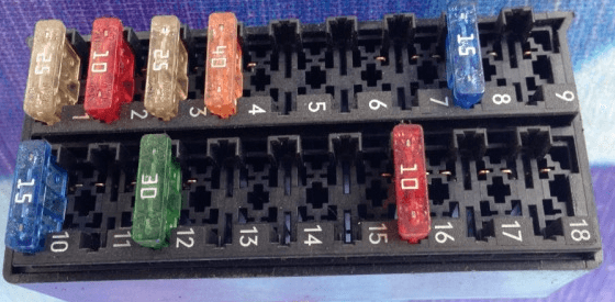
General view.
| Diagram | |
|---|---|

|
|
| № | Amps / Diagram |
| 1 | 25A driver's door control unit |
| 2 | 10A Diagnostic connector (T16 / 16) |
| 3 | 25A ABS control unit |
| 4 | 40A ABS control unit |
| 5 | Reserve |
| 6 | Reserve |
| 7 | 30A headlight washer pump |
| 8 | 15A anti-theft alarm relay 1 |
| 9 | Reserve |
| 10 | 15A control unit with display for radio and navigation system |
| 11 | 7.5A mobile phone control electronics control unit, tachograph control unit |
| 12 | 30A heating switch and changing heating power, supply air fan relay |
| 13 | 7,5A auxiliary heater timer |
| 14 | 30A driver's seat heating regulator, front passenger seat heating regulator |
| 15 | 10A load platform lighting switch |
| 16 | 10A heating switch and heating power change, air conditioner control unit, CD changer |
| 17 | 10A indoor light switch |
| 18 | Reserve |
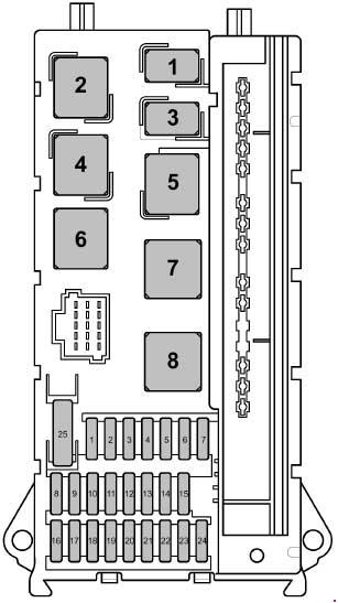
Fuse box -SC-
General view.
| Diagram | |
|---|---|
|
|
| № | Amps / Legend |
| 1 | 15A High tone horn |
| 2 | 25A Electronic ignition lock Control unit el. steering column lock |
| 3 |
|
| 4 | 5A Light switch Central control panel of the front panel |
| 5 | 30A Wiper motor |
| 6 | 15A Booster fuel pump |
| 7 | 5A Steering column control unit |
| 8 | 20A Engine control unit |
| 9 |
|
| 10 |
|
| 11 | 15A Unloading relay 2, terminals 15 (only for vehicles of the weight class 3.8 t) Fuse 1 in fuse holder D Fuse 2 in fuse holder D |
| 12 | 10A Airbag control unit |
| 13 | 15A Stowage compartment lighting switch Cigarette lighter |
| 14 | 5A Light switch Control unit in instrument cluster Diagnostic connector |
| 15 | 5A Heater switch and operating mode selection Headlamp leveling adjuster Actuator motor for headlight range control for left and right |
| 16 |
|
| 17 | 10A Airbag control unit |
| 18 |
|
| 19 | 7.5A Onboard supply control unit (interior lighting) |
| 20 | 25A Onboard supply control unit |
| 21 |
|
| 22 |
|
| 23 | 25A Starter Onboard supply control unit |
| 24 | 10A Reserve, terminal -15- Battery regulation system control unit (from May 2013) |
| 25 | 30A 12V socket |
| 1 | Horn relay |
| 2 | Wiper motor changeover relay 2 |
| 3 | Fuel pump relay |
| 4 | Wiper motor changeover relay 1 |
| 5 | Power supply relay, cl. 50 |
| 6 | Power supply relay terminal 15 |
| 7 | Relay for power supply of electronic components of the engine |
| 8 | Power supply relay 2, cl. 15 |
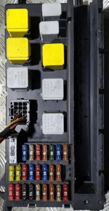
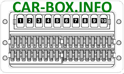
Fuse box -SD-
Located under the driver's seat.

Photo example.
Type 1
Diagram.
|
|
| № | Amps / Legend |
| 1 | 5A Driver's door power window control panel Heated rear window relay (up to June 2006) Heated rear window relay 2 (from July 2006) |
| 2 | 30A Swing door rear window wiper motor |
| 3 | 5A Timer Gearbox neutral switch Display control unit Control unit for mobile phone control electronics (up to May 2011) Rear view camera |
| 4 | 7.5A Switch for adjusting the operating speed (from July 2006) Control sensor for power take-off (from July 2006) Heated rear window relay (up to June 2006) Trailer detection control unit Tachograph control unit (from July 2006) |
| 5 | 5 / 10A Selector Control unit mech. Electronically controlled gearbox |
| 6 | 5A Battery regulation control unit (up to May 2013) Crankcase ventilation heating resistor |
| 7 | 10A Fuel filter heating element |
| 8 | 5 / 10A Button for tipping device Special superstructure relay, cl. 15 Plug, 6-pin (from May 2007) Plug, 7-pin (tail lift connector) |
| 9 | 15A Roof fan switch for supply ventilation of the cargo compartment, Siren relay |
| 10 | 25A For a manufacturer of superstructures and special equipment |
| 11 | 15A Relay for special superstructures, cl. 15 |
| 12 | 10A Relay for special superstructures, cl. 61 |
| 13 | 10 / 30A Evaporator fan control unit (from May 2007 to May 2011) Relay for repeaters, direction indicators on the roof (until May 2007) |
| 14 | 20A Trailer recognition control unit (up to August 2006) Connector, 9-pin (preparation for post-factory installation of trailer hitch from September 2006) Hitch socket (from September 2006) |
| 15 | 25A Trailer recognition control unit |
| 16 | 7.5A Parking aid control unit Tire pressure monitor control unit |
| 17 | 25A Control unit for programmable special functions |
| 18 | 25A Control unit for programmable special functions |
| 19 | 5 / 25A Roof electrical control unit |
| 20 | 7.5 / 10A Coolant circulation relay after off. Engine Entrance and Footwell Light Relay (from May 2009,) |
| 21 | 15 / 30A Rear window defogger relay |
| 22 | 15A Rear window heating relay (up to June 2006) Rear window heating relay 2 |
| 23 | 10 / 15A Load box lighting switch (from November 2008) 12V socket 2 |
| 24 | 15A Socket 12V 4 |
| 25 | 15A Socket 12V 3 |
| 26 | 25A Additional heater control unit |
| 27 | 20 / 25A Additional heater control unit |
| 28 | 30 / 40A Evaporator fan control unit (up to April 2007) Gearbox hydraulic pump relay (from May 2007) |
| 29 | 15A Control unit mech. Electronically controlled gearbox |
| 30 | 40A Gearbox hydraulic pump relay (up to April 2007) Battery regulation control unit |
| 31 | 15 / 30A Control unit for rear intake fan Control unit for left sliding door Rear intake fan |
| 32 | 5A Control unit for battery control |
| 33 | 15A Right sliding door control unit |
| 34 | 15A Reductant heating system control unit (from April 2009) |
| 35 | 30 / 15А Control unit for reducing agent heating system (from April 2009) |
| 36 | Not used |
| Relay units: 1 - Relay for special superstructures, cl. 15 2 - Relay for special superstructures, cl. 61 3 - Interior lighting relay, Tipping device relay (up to October 2007), Tailgate relay 4 - Headlight cleaning relay 5 - Rotating beacon relay 6 - Anti-theft alarm relay 1 7 - Coolant pump relay 8 - Coolant circulation relay after off engine 9 - Siren relay 1 - Not used |
|
Type 2
Diagram.

|
|
| № | Amps / Description |
| 1 | 5A Window regulator control panel in the driver's door Relay 2 for heated rear window |
| 2 | 30A Rear window wiper motor in swing door |
| 3 | 5A Timer Gearbox neutral position switch Display panel Rearview camera |
| 4 | 7.5A Switch for adjusting the working speed PTO monitor sensor Trailer detection control unit Tachograph control unit |
| 5 | 5 / 10A Selector Control unit mech. Electronically controlled gearbox Bonnet switch (from November 2011) |
| 6 | 5 / 10A Heating resistor for crankcase ventilation system Control unit for battery regulation (from May 2011 to May 2013) |
| 7 | 10A Fuel filter heating element |
| 8 | 5 / 10A Tipping device button Parking aid control unit (from May 2013) Special superstructure relay, cl. 15 (up to November 2011) Connector, 6-pin -T6ah- Connector, 7-pin -T7f- (tail lift connector) |
| 9 | 15A Roof fan switch for supply ventilation of the cargo compartment (until November 2011) Siren relay (until November 2011) Not used (from November 2011) |
| 10 | 25A For a manufacturer of superstructures and special equipment |
| 11 | 15A Relay for special superstructures, cl. 15 |
| 12 | 10A Relay for special superstructures, cl. 61 |
| 13 | Reserve |
| 14 | 20A Connector, 9-pin -T9b- (preparation for post-factory installation of trailer hitch) Hitch socket |
| 15 | 25A Trailer recognition control unit |
| 16 | 7.5A Parking aid control unit Tire pressure monitor control unit |
| 17 | 25A Control unit for programmable special functions |
| 18 | 25A Control unit for programmable special functions |
| 19 | 5 / 25A Roof electrical control unit |
| 20 | 7.5 / 10A Coolant circulation relay after off. motor relay input illumination and footwell |
| 21 | 30A Rear window defogger relay |
| 22 | 15A Rear window heating relay 2 |
| 23 | 10 / 15A Load box lighting switch 12 V socket 2 -U18- |
| 24 | 15A Socket 12V 4 |
| 25 | 15A Socket 12V 3 |
| 26 | 25A Additional heater control unit |
| 27 | 20 / 25A Additional heater control unit |
| 28 | 30 / 40A Gearbox hydraulic pump relay, Starter relay 1 |
| 29 | 15A Control unit mech. Electronically controlled gearbox |
| 30 | 5A Control unit for battery regulation system |
| 31 | 15 / 30A Control unit for left sliding door (from May 2012) Control unit for rear supply fan Rear supply fan |
| 32 | 5A Control unit for battery control |
| 33 | 7.5 / 15 / 30A Not used Right sliding door control unit (from May 2012) Transfer case interlock relay (from January 2012) Air compressor (from January 2012) |
| 34 | 7,5 / 15А Reductant heating system control unit Gearbox sensor for differential lock |
| 35 | 3 / 15А Control unit for reducing agent heating system Control unit for pneumatic compressor protection (from January 2012) |
| 36 | 5A Not used (until January 2012) Compressor switch (from January 2012) |
| 37 | Reserve |
| 38 | Reserve |
| 39 | 7.5 / 15A Roof fan switch for fresh air in the cargo compartment (from November 2011) Siren relay (from November 2011) |
| 40 | Reserve |
| 41 | Reserve |
| 42 | 30A Evaporator fan control unit -J349- |
| 43 | Reserve |
| 44 | Reserve |
| 45 | Reserve |
| 46 | Reserve |
| 47 | Reserve |
| 48 | Reserve |
| 49 | Reserve |
| 50 | Reserve |
| 51 | Reserve |
| 52 | Reserve |
| 53 | Reserve |
| 54 | Reserve |
| 55 | Reserve |
| 56 | Reserve |
Additional fuses
Located under the drivers seat.
| Diagram | |
|---|---|

|
|
| № | Circuit Protected |
| A | Battery isolation relay |
| B | Starter relay 1 |
| C | Starter relay 2 |
| 1 | Not used |
| 2 | Relay for unloading cl. 15 |
| 3 |
|
| 4 |
|
| 5 | Heated rear window relay |
| 6 | Heated rear window relay 2 |
| 7 | Relay, unloading 2 terminals 15 |
| 8 | Not used |
| 9 | Heated windscreen relay |
| 10 | Supply fan relay |
| 11 | Not used |
| 12 | Not used |
| 13 | Not used |
| 14 | Not used |
| 15 | Relay for special superstructures, cl. 15 |
| 16 | Relay for special superstructures, cl. 61 |
| 17 | Tailgate relay Interior lighting relay |
| 18 | Relay for headlamp cleaning system Relay for unlocking pneumatic compressor |
| 19 |
|
| 20 | Anti-theft alarm relay 1 |
| 21 | Coolant pump relay |
| 22 | Coolant circulation relay after off engine |
| 23 | Siren relay ABS cut-off relay |
| 24 | Relay blocking 1 transfer case |
| 25 | Locking relay 2 transfer case |
| 26 | Relay for reversing warning device shutdown Relay for blocking 3 transfer case |
