B5 is a model of the 5th generation of cars of the Passat family. Produced in 1997, 1998, 1999, 2000, 2001, 2002, 2003, 2004 and 2005. After the 2001 update, the people received the name Passat B5 + or Passat GP. In this article we will present a description of the fuses and relays of the Volkswagen Passat B5, complete block diagrams with the purpose of the elements and a photo of an example of execution. Separately, we highlight the fuse for the cigarette lighter and the fuel pump.
The current designation of fuses and relays may differ from the one shown and depends on the equipment and year of manufacture of the vehicle.
In passenger compartment
Fuse box
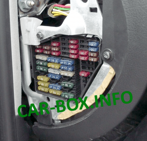
It is located at the end of the instrument panel on the driver's side behind the protective cover. On the back of the cover there must be an up-to-date fuse assignment diagram or a description brochure.
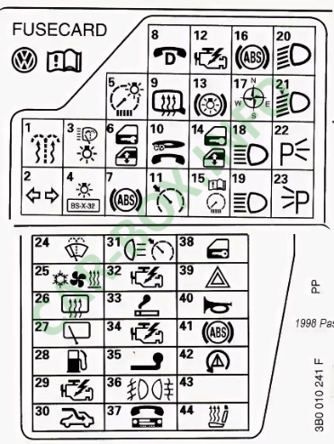
| Diagram | |
|---|---|
|
|
| № | Amps / Description |
| 1 | 5A Heated washer nozzles |
| 2 | 10A Turn Signals (flasher) |
| 3 | 5A P comfort system, cruise control, climate control, air conditioning, seat heating control modules, day / night light mirror, control module and multifunction steering wheel control unit |
| 4 | 5A License plate lamps |
| 5 | 10A Instrument panel, heated seats, automatic transmission display, mirror switch, pump Airbag outside temperature gauge, navigation system, parking lights |
| 6 | 5A Central locking, reading lamps |
| 7 | 10A ABS system or Reversing lights, Speedometer, Vehicle speed sensor |
| 8 | 5A Phone |
| 9 | 10A Heated mirrors and door locks |
| 10 | 5A Headlight range control, CD - changer |
| 11 | 5A Cruise control [automatic transmission], instrument cluster |
| 12 | 10A Built-in diagnostics |
| 13 | 10A Stop lights |
| 14 | 10A Interior lighting, reading lamps, anti-theft system, passenger visor mirror |
| 15 | 10A Instrument panel, automatic transmission, air conditioning, navigation system |
| 16 | 5A ABS system |
| 17 | 10A Heated door locks |
| 18 | 10A Right high beam |
| 19 | 10A Left high beam |
| 20 | 15A Right low beam, headlight corrector |
| 21 | 15A Left low beam, headlight corrector |
| 22 | 5A Right side lights |
| 23 | 5A Left side lights |
| 24 | 25A Windshield wipers, washer pump. Wiper breaker relay |
| 25 | 30A Heater fan, air conditioner |
| 26 | 30A Heated rear window, heated mirrors, air recirculation |
| 27 | 15A Rear wiper |
| 28 | 15A Fuel pump |
| 29 | 15A Engine management |
| 30 | 20A Electric sunroof |
| 31 | 20 / 15А Reversing lights, cruise control, automatic transmission, diagnostic socket |
| 32 | 20A Engine management |
| 33 | 15A Cigarette lighter fuse |
| 34 | 15A Engine management (ignition / injection) |
| 35 | 30A Trailer socket |
| 36 | 15A Fog lights |
| 37 | 15A Telephone, radio |
| 38 | 15A Adjustment of mirrors. Remote unlocking of the fuel filler flap. Window lifters. Central locking. |
| 39 | 15A Emergency lighting (emergency gang) |
| 40 | 25A Signal |
| 41 | 25A ABS system (hydro modulator / pump) or additional cigarette lighter |
| 42 | 40A Auxiliary Air Fan 25A Radio |
| 43 | 5A S-terminal 10A Motor controls |
| 44 | 30 / 15A Heated seats |
Fuse number 33 at 15A is responsible for the cigarette lighter. And for a gas pump - 28 to 15A. Recall that several more elements are also responsible for the fuel supply.
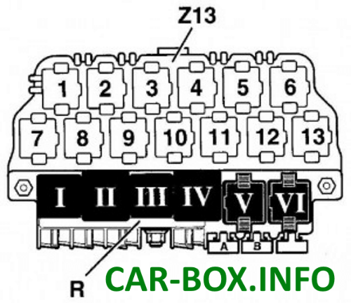
Main relay box
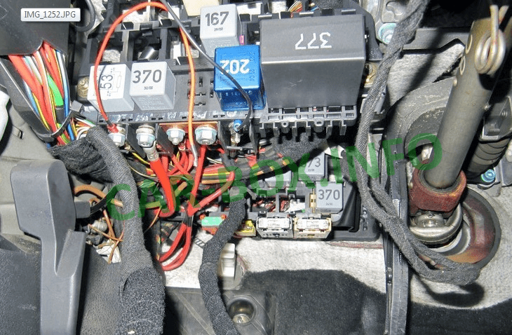
It is located under the dash on the driver's side, not far from the steering rack.
| Diagram | |
|---|---|
|
|
| № | Panel R |
| I | Horn relay |
| II | Auxiliary relay contact X |
| III | Wiper relay |
| IV | Fuel pump relay |
| Glow plug relay | |
| V | Free |
| VI | |
| A | Fuse |
| B | |
| № | Panel Z |
| 1 | Radiator Fan Relay (Air Conditioning) |
| 2 | Clutch Relay |
| 3 | Magnetic Clutch Relay (Air Conditioning) |
| 4 | Air conditioner relay |
| 5 | Fuel pump relay for diesel engines |
| 6 | External lighting relay |
| Taxi equipment | |
| 7 | Headlight relay |
| 8 | Glow plug relay |
| 9 | Free |
| 10 | Fog lamp relay |
| 11 | Communication relay |
| 12 | Starter relay |
| 13 | Starter lock relay |
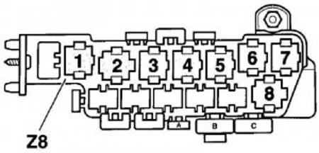
Additional relay box

Installed on cars with an increased level of electrical equipment and is called eight - pin. Located behind the main relay box.
| Diagram | |
|---|---|
|
|
| № | Description |
| 1 | Free |
| 2 | Relay ABS / EDS / ESC |
| 3 | Relay ABS / EDS / ESC |
| 4 | Fan relay 80 W |
| Fan relay 300 W, 1 stage | |
| 5 | Fan relay for maximum speed |
| 6 | Fan relay 300 W, stage 2 |
| A | Fan fuse, 5A |
| B | Fan fuse, 30A |
| C | Hydraulic pump fuse, 50A |
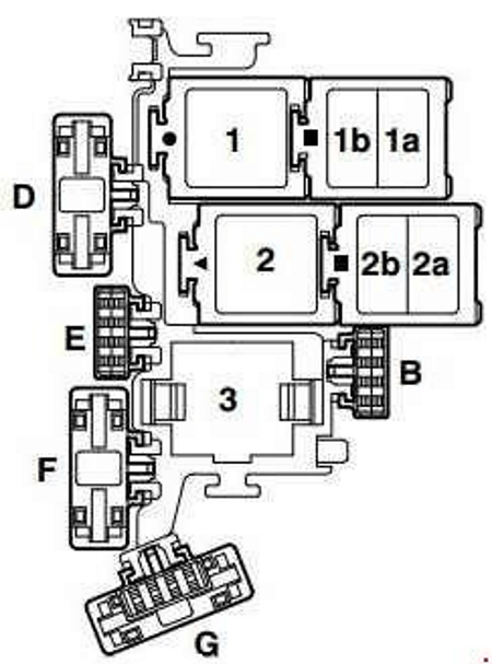
In the engine compartment
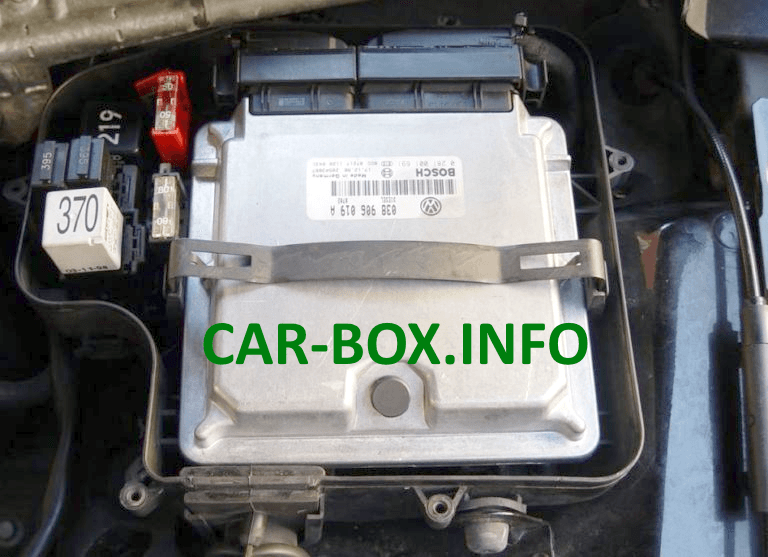
Fuse panel located under the protective cover next to the control box.
| Diagram | |
|---|---|
|
|
| № | Amps / Description |
| B | 10A Fuse for injectors (S116) |
| B | 5A Auxiliary engine coolant pump fuse |
| D | 50A Secondary air pump fuse (S130) |
| E | 40A Fuse for ignition coil terminal (S115) |
| F | 5A Fuse for engine control module (ECM) (S102) |
| G | 10A Fuse for engine electronics (S282) |
| 1 | Motronic Engine Control Module Power Relay (167), engine code BDP |
| 2 | Secondary air pump relay (AIR) (373), (100) |
| 3 | Motronic Engine Control Module Power Supply (429), (219) / Auxiliary Coolant Pump Relay (EC) (53), (411) |
