Volkswagen Touareg is a mid-size crossover that has been produced in 3 generations from 2002 to the present with both gasoline and diesel engines. Years of production of the first generation: 2003, 2004, 2005, 2006, 2007, 2008, 2009 and 2010. During this time, the car received a facelift. The 2nd generation was produced in 2011, 2012, 2013, 2014, 2015 and 2016. After that, the third generation of Touareg entered the assembly lines of the Volkswagen concern. In our material you will find a description of fuses and relays Volkswagen Tuareg 1st (GP) generation with photos and block diagrams in which they are located. Separately, we note the fuse responsible for the cigarette lighter.
The purpose of the elements in your blocks may differ from the one presented and depends on the year of manufacture and the level of electrical equipment of the car.
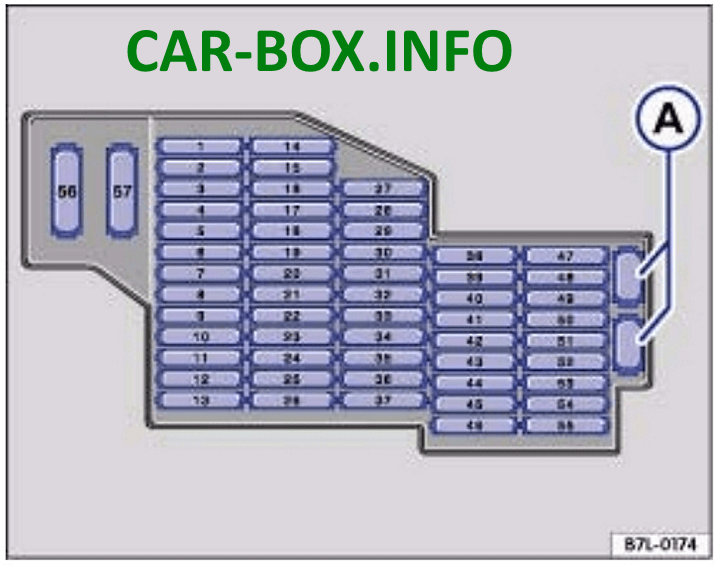
In the passenger compartment
On the left side of the dashboard
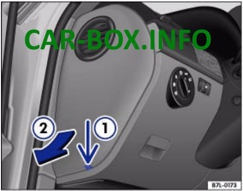
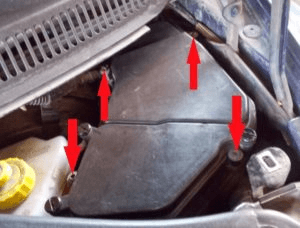
Remove the protective cover for access.
| Diagram | |
|---|---|
|
|
| № | Amps / Description |
| 1 | 20A Cigarette lighter |
| 2 | 5A Parking heating (clock, sensor, pump) 15A Circulation pump relay |
| 3 | 20A Additional sockets (12V) |
| 4 | 20A Parking heating - heater |
| 5 | 20A Socket relay |
| 6 | 15А KESSY |
| 7 | 5A Diagnostics, multiplex system, rain and light sensor |
| 8 | 30A Wipers |
| 9 | 15A Glass washer pump |
| 10 | 25A Window Regulator - Left Rear |
| 11 | 15A Central locking - left |
| 12 | 20A Interior lighting |
| 13 | - |
| 14 | 25A Window Regulator - Left Front |
| 15 | 20A Left rear lamp |
| 16 | 20A Sound signal |
| 17 | 10A Direction indicator, parking lights - left |
| 18 | 20A Relay SRA |
| 19 | 15A Fog lights |
| 20 | 30A Power seat |
| 21 | 15A Additional turning headlight |
| 22 | 30A Lateral locking, trunk lid control unit 2 |
| 23 | 10A Rear transverse locking |
| 24 | 5A Tire pressure monitoring system |
| 25 | 15A Steering column adjustment - electro |
| 26 | 10A Airbag control unit, Front passenger airbag deactivation, clutch pedal switch |
| 27 | 5A Switch for turning off the interior protection system, interior lighting |
| 28-32 | Reserve |
| 33 | 15A Steering wheel heater, steering column control unit |
| 34 | 5A Seat heating sensor, Security monitoring of the interior space |
| 35 | 15A Dipped beam, high beam 30A Onboard supply control unit |
| 36 | 10A Powered by onboard battery |
| 37 | - |
| 38 | 10A Brake signals |
| 39 | 5A Relay for ignition system, air conditioning, seat heating, instrument panel |
| 40 | 5A Instrument panel |
| 41 | 15А KESSY |
| 42 | 30A Electro hatch |
| 43 | 30A Subwoofer |
| 44 | 30A Electro seat device |
| 45 | 30A Electro seat device |
| 46 | - |
| 47 | 10A Cross-axle differential lock control unit |
| 48 | 5A Parking heating clock, lane change assist control unit |
| 49 | 5A Servotronic |
| 50 | 10A Oil level and temperature sensor, Blowing heater pipe (VR6) |
| 51 | 5A Air Quality Sensor, Tire Pressure Monitoring System, Diagnostics |
| 52 | 30A Rear wiper |
| 53 | 5A Security monitoring of the interior of the passenger compartment, External lighting switching unit, Heated mirrors |
| 54 | 10A Headlight range control |
| 55 | 15A supply fan relay (speed 2) |
| 56 | 40A Climate control |
| 57 | 40A Bitron fan adjustment motor |
| A | spare fuses |
For cigarette lighter fuses with numbers 1, 3 and 5 are responsible for 20A.
Fuse number 1 is: cigarette lighter + 12v socket in the central tunnel for rear passengers. Fuse # 3 is: a 12v socket in the luggage compartment (in the wall on the right), the one that is closer to the fifth door. Fuse No. 5 is: 12v driver's socket (near the automatic transmission handle) and a 12v socket in the luggage compartment (in the wall on the right).
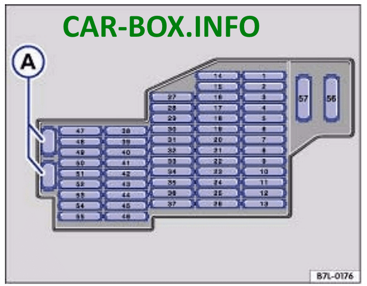
On the right side of the dashboard

Located in the right end of the dashboard, it is also covered with a protective cover.
| Diagram | |
|---|---|
|
|
| № | Amps / Description |
| 1 | 15A Trailer Recognition Control Unit |
| 2 | 5A Parktronic, Compass |
| 3 | 15A Trailer control unit |
| 4 | 5A Phone |
| 5 | 15A Trailer recognition control unit |
| 6 | 30A Anti-slip system ESP, ABS |
| 7 | 5A Transfer case control unit |
| 8 | 20A Additional high beam headlights |
| 9 | 5A CD changer |
| 10 | 5A TV tuner |
| 11 | 10A Radio |
| 12 | 30A Audio Amplifier, Antenna Switch |
| 13 | - |
| 14 | 20A Right rear lamp, 15A luggage compartment lid control unit |
| 15 | 25A Window Regulator - Right Rear |
| 16 | 10A Trunk lighting |
| 17 | 15A Low beam, High beam |
| 18 | 30A Rear window defogger relay |
| 19 | 25 / 30A Traction hitch tilt motor |
| 20 | 30A Electric seat adjustment 20A Inverter with socket, 12V-230V |
| 21 | 10A Security alarm system, Spare wheel unlocking |
| 22 | 25 / 30A Electrically adjustable front right seat, Heated front seats |
| 23 | 10A Climate control |
| 24 | 25 / 30A Electro seat adjustment |
| 25 | 5A Rear climate control console |
| 26 | - |
| 27 | 15A Tire pressure monitoring system, Ride height control control unit |
| 28 | 10A Automatic distance keeping |
| 29 | 10A Automatic transmission (automatic transmission) |
| 30 | 20A Winch, closer relay |
| 31 | 25A Rear control unit, 15A Rear lid control unit |
| 32 | 10A Central locking - right |
| 33 | 10A Rear alarm control unit 15A Individual equipment |
| 34 | 25A Window Regulator - Right Front |
| 35 | 10A Direction indicator, parking lights right 30A Control panel for front passenger seat adjustment |
| 36 | 5A Ceiling module, Telephone |
| 37 | - |
| 38 | EPS, ABS |
| 39 | 10A Climate control 5A Relay for windscreen heating element |
| 40 | 10A Longitudinal blocking |
| 41 | 10A Trailer control unit |
| 42 | 5A Radio, Garage door opener control |
| 43 | 5A Reversing light switch |
| 44 | Heated washer jets, seat heating control |
| 45 | Reserve |
| 46 | Reserve |
| 47 | 10A Automatic distance control, radar sensor, right headlight module |
| 48 | 10A Air suspension control unit |
| 49 | 5A Mirror, Telephone |
| 50 | 5A Parktronic, switch off ASR and ESP |
| 51 | 20A Gearbox |
| 52 | 5A Selector |
| 53 | 30A Windshield heater relay |
| 54 | 30A Electric trailer brakes, Windshield heater relay |
| 55 | 20A Electric steering column |
| 56 | 40A ABS, ESP |
| 57 | 40A Longitudinal blocking |
Block under the driver's seat
Located on or near the battery cover.
| Diagram | |
|---|---|

|
|
| № | Amps / Legend |
| 1 | Main battery switch |
| 2 | Power supply relay terminal 15 (100) / (433) |
| 3 | Second battery charging relay |
| SD1 | 150A Left fuse box |
| SD2 | 150A Right fuse box |
| SD3 | 60A Right fuse box |
| SD4 | 60A Switching block, left fuse box |
| SD5 | 60A Terminal 15 relay |
| SD7 | 250A Parallel connection of the battery |
| SD8 | 150A Socket |
| SD9 | 5A Onboard supply control unit |
| SD10 | 10A Onboard supply control unit |
| SD11 | 5A Starter wire diagnosis |
| SD12 | Not used |
| SD13 | 40A The electric motor of the compressor of the ride height control system |
| SD14 | Not used |
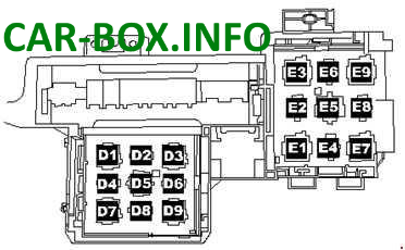
Under-dash relay box
It is located under the front panel on the left.
|
|
| № | Description |
| D1 | Servotronic control unit (476) |
| D2 | Closer relay (404) |
| D3 | Ride height control compressor relay (373) |
| D4 | Socket relay (404) |
| D5 | Air conditioning relay (100) |
| D6 | Supply fan relay, speed 2 (404) only with manual air conditioning |
| D7 | Heated rear window relay (53) |
| D8 | Circulation pump relay (404) VR6 only with auxiliary heater |
| D9 | Alternator connection relay (53) |
| E1 | Solar Battery Isolator Relay (79) |
| E2 | Spare wheel release relay (404) |
| E3 | Left windscreen heater relay (53) |
| E4 | Circulation pump relay (404) |
| E5 | Power supply relay 2 terminal (432) V10 TDI only |
| E6 | Not used |
| E7 | Headlamp cleaning relay (53) |
| E8 | Residual heat accumulator relay (404) |
| E9 | Heated front windscreen relay (53) |
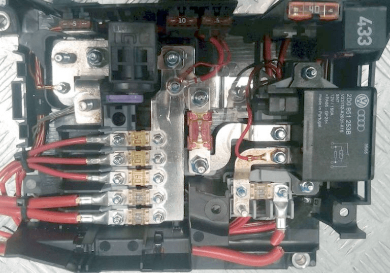
In the engine compartment
This relay and fuse box is located in the air intake compartment of the engine compartment.
| Diagram | |
|---|---|

|
|
| № | Amps / Description |
| 1 | 60A radiator fan control unit, radiator fan |
| 2 | 30A radiator fan control unit, radiator fan |
| 3 | 40A secondary air pump |
| 4 | 40A secondary air pump |
| 5 | 30A ignition coil, fuses in relay and fuse box |
| 6 | 30A ignition coil |
| 7 | 10A Cylinder Injector, Fuel Cooling Pump Relay 20A Ignition Coil |
| 8 | 10A injector cylinder 20A ignition coil |
| 9 | 30A Motronic control unit, engine control unit, diesel injection control unit |
| 10 | 10A high pressure sensor, air mass meter, air conditioning control unit, alternator connection relay, auxiliary coolant pump relay, brake booster relay (3.2 l), fuel system diagnostic pump, turbocharger control unit |
| 11 | 15A oil level and temperature sensor, Climatronic control unit, absorber solenoid valve, turbocharger control unit 10A Air conditioning control unit |
| 12 | 5A secondary air pump relay, electric fuel pump relay 10A absorber solenoid valve 1, regulator, glow plug control unit 20A coolant thermostat electronically controlled engine, high pressure sensor, coolant circulation relay after off. engine, air conditioning control unit, intake camshaft adjuster valve, intake manifold geometry change motor |
| 13 | 15A fuel pressure regulator, fuel pump |
| 14 | 15A fuel pressure regulator, fuel pump 10A fuel metering valve |
| 15 | 15A fuel pump relay, Motronic control unit, engine control unit |
| 16 | 10A parallel battery relay, 30A brake pump |
| 17 | 15A lambda probe 30A lambda probe |
| 18 | 7.5 / 15A lambda probe after catalyst |
| A1 | Glow plug control unit (475) |
| A2 | Terminal 30 power supply relay (109) / (219) |
| A4 | Fuel pump relay (53) |
| A6 | Fuel cooling pump relay (404) |
| A5 | Additional coolant pump relay (404) |
| A3 | Glow plug control unit (475) |
| B6 | Additional fuel pump relay (449) |
| B7 | Not used |
| B4 | Low heating power relay (100) Power supply relay 1 (100) |
| B3 | High power heating relay (100) |
| B1 | Terminal 30 power supply relay (219) |
| B2 | Fuel pump relay (53) |
| C20 | Terminal 50 power supply relay (433) |
| C19 | Fuel boost pump relay (404) |

Windshield spray fuse for 2003 Volkswagen Touareg