The H2 is an American General Motors SUV sold under the brand since 2002 at a purpose-built plant in Mishawaka, Indiana, United States. In this article, we will take a detailed look at the fuse box diagrams for the Hummer H2 (first generation; restyiling): 2008, 2009, 2010 years of manufacture.

Here you will find the locations and photos of distribution boxes. The fuses responsible for the “Cigarette lighter” and “Fuel Pump” are highlighted in bold.
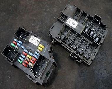
In the engine compartment

Located on the driver's side near the battery, behind the plastic cover.
| Diagram | ||
|---|---|---|

|
||
| No. | Description | Amps |
| Non-Serviceable | ||
| R11 | Back-Up Lamps | |
| R12 | Daytime Running Lamps (DRL) | |
| R13 | Right Cooling Fan | |
| R14 | Right Cooling Fan, Cooling Fan Control | |
| R15 | Left Cooling Fan | |
| R16 | Front Washer Fluid Pump | |
| R17 | High Beam Headlamp | |
| R18 | Horn (beep) | |
| R19 | Unlocking the liftgate | |
| R20 | Rear washer fluid pump | |
| R21 | "FWD", "HTR STR/WHL" | |
| R22 | Left Trailer Stop Lamp | |
| R23 | Right Trailer Stop Lamp | |
| R24 | Wiper | |
| R25 | Windshield Wiper Motor | |
| Relays | ||
| R1 | High Speed Cooling Fan Relay | |
| R2 | Low Speed Cooling Fan Relay | |
| R3 | Cooling Fan Control | |
| R4 | Dipped Beam Headlamp Relay | |
| R5 | Air Conditioning Compressor Relay | |
| R6 | Starter Relay | |
| R7 | Powertrain Control Module (PCM) Relay | |
| R8 | Parking light relay | |
| R9 | Rear Window Defogger Relay | |
| R10 | Switched Power | |
| Fuses | ||
| 1 | Left trailer stop/turn light | 10 A |
| 2 | Air temperature sensor (IAT), exhaust gas canister purge solenoid valve (EVAP) | 15 A |
| 3 | Engine Control Module (ECM) | 15 A |
| 4 | Right trailer stop/turn light | 10 A |
| 5 | Front Washer Fluid Pump | 15 A |
| 6 | Oxygen Sensors | 10 A |
| 7 | Vehicle Stability System, Antilock Brake System (ABS module) | 30 A |
| 8 | Trailer Back-Up Lamps | 10 A |
| 9 | Dipped Beam Left Headlamp | 10 A |
| 10 | Engine Control Module (ECM) | 10 A |
| 11 | Fuel Injectors, Ignition Coils (Right) | 20 A |
| 12 | Transmission control module, exhaust gas canister vent solenoid valve (EVAP) | 15 A |
| 13 | Back-Up Lamps | 10 A |
| 14 | Dipped Beam Right Headlamp | 10 A |
| 15 | Air conditioner compressor clutch | 10 A |
| 16 | Oxygen Sensors | 10 A |
| 17 | Transmission Controls (Ignition) | 15 A |
| 18 | Hummer H2 Fuel Pump Fuse, Engine Control Module (ECM) | 20 A |
| 19 | Rear Washer Fluid Pump | 15 A |
| 20 | Fuel Injectors, Ignition Coils (Left Side) | 20 A |
| 21 | Trailer Parking Lamps | 15 A |
| 22 | Parking Lamps (left side) | 15 A |
| 23 | Parking Lamps (right side) | 15 A |
| 24 | Horn (beep) | 15 A |
| 25 | High Beam Right Headlamp | 10 A |
| 26 | Daytime Running Lamps (DRL) | 10 A |
| 27 | High Beam Left Headlamp | 10 A |
| 28 | Sunroof | 30 A |
| 29 | Key Ignition System, Theft Deterrent System | 2 A |
| 30 | Windshield Wiper | 25 A |
| 31 | Provision of upfitter services | 30 A |
| 32 | Electrically Controlled Air Suspension | 15 A |
| 33 | Climate Controls (HVAC) | 10 A |
| 34 | Safety Airbag System | 10 A |
| 35 | Audio Amplifier | 30 A |
| 36 | Audio system, audio controller for rear seats, digital radio receiver | 15 A |
| 37 | Miscellaneous, Cruise Control, Rear Vision Camera | 10 A |
| 38 | Safety Airbag System | 15 A |
| 39 | Instrument Panel Cluster, Body Control Module (BCM) | 10 A |
| 40 | Run, Accessory, Midgate Module | 10 A |
| 41 | Auxiliary Climate Control Unit | 10 A |
| 42 |
|
30 A |
| 43 | Provision of upfitter services | 15 A |
| 44 | Hummer H2 Cigarette Lighter Fuse, Auxiliary 12V Power Outlet, Data Link Connector (DLC) | 15 A |
| 45 | Upfitter Provision, Special Equipment Option (SEO) | 10 A |
| 46 | Climate Controls | 10 A |
| 47 |
|
15 A |
| 50 | Low Speed Cooling Fan Relay | 40 A |
| 51 | Electronically Controlled Air Suspension Relay | 60 A |
| 52 | Vehicle Stability System, Antilock Brake System (ABS) | 60 A |
| 53 | High Speed Cooling Fan Relay | 40 A |
| 54 | Starter Relay | 40 A |
| 55 | Trailer Brake Module | 30 A |
| 56 | Electric center left | 60 A |
| 57 | Heated Windshield Washer System | 60 A |
| 58 | 4-Wheel Drive System | 30 A |
| 59 | Trailer Connector Battery Power | 40 A |
| 60 | Bussed Electrical Center Mid #1 | 60 A |
| 61 | Climate Control Blower | 40 A |
| 62 | Bussed Electrical Center Left #2 | 60 A |
In the passenger compartment
The first fuse box is located at the edge of the dashboard on the driver's side. The second fuse box is located to the left of the steering wheel, under the instrument panel.
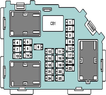
Fuse box #1
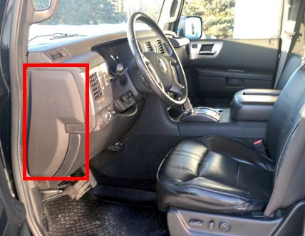
Located at the end of the dashboard on the driver's side.
General view of the Hummer H2 cabin fuse box.
| Diagram | ||
|---|---|---|
|
||
| No. | Description | Amps |
| CB1 | Driver Side Power Window | 25 A |
| R1 | Power Door Lock Relay (Non-Serviceable) | |
| 1 | Rear seat heater control module | 20 A |
| 2 | Rear Cargo Accessory Power Outlets | 20 A |
| 3 | Illuminated steering wheel controls | 2 A |
| 4 | Driver Door Module | 15 A |
| 5 | Dome lamps, front passenger side turn signal, body control module (BCM) | 15 A |
| 6 | Driver's side turn signal and brake light, body control module (BCM) | 15 A |
| 7 | Rear instrument panel illumination, body control module (BCM) | 10 A |
| 8 | Passenger side turn signal | 15 A |
| 9 | Passenger Door Module | 10 A |
| 10 | Power Door Lock #2 (Unlock) | 15 A |
| 11 | Power Door Lock #2 (Lock) | 15 A |
| 12 | Stop lamps, center high-mounted brake light, body control module (BCM) | 15 A |
| 13 | Rear Climate Controls | 30 A |
| 14 | Empty | - |
| 15 | Body Control Module (BCM) | 15 A |
| 16 | Floor Console 12V Power Outlets, Cigar Lighter Fuse | 20 A |
| 17 | Interior Lamps, Body Control Module (BCM) | 10 A |
| 18 | Power Door Lock #1 (Unlock) | 15 A |
| 19 | Infotainment system (video display), remote keyless entry system | 5 A |
| 20 | Universal home remote control (garage door opener) | 10 A |
| 21 | Power Door Lock #1 (Lock) | 15 A |
| 22 | Vehicle Communication Interface Module (OnStar® System) | 10 A |
| 23 | Window Wiper Motor (Rear) | 25 A |
| 24 | Empty | - |
| 25 | Driver Seat Module | 10 A |
Fuse box #2
Located under the dashboard, to the left of the steering column.
| Diagram | ||
|---|---|---|

|
||
| No. | Description | Amps |
| CB1 | Power Window Passenger Side | 25 A |
| CB2 | Passenger Seat | 25 A |
| CB3 | Driver Seat | 25 A |
| CB4 | Rear Sliding Window | 25 A |
| R1 | Multifunction Switch (PARK ENABLE PCB) *Non-Serviceable Relay* | |
