
This full-size crossover featuring an eight-passenger cabin was unveiled by Honda at the 2002 North American International Auto Show (Detroit). Unlike the Passport, which was based on the Isuzu Rodeo, this vehicle was engineered entirely in-house. Built on the same platform as the Acura MDX, it features more traditional SUV styling. In this article, we take a detailed look at the fuse box diagrams for the first-generation Honda Pilot (Mid-size SUV platform; code YF1 / YF2), produced from 2002 through 2008.
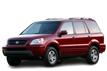
Below you will find power distribution box locations, layout diagrams, and photos. Fuse locations for the "Cigarette Lighter" and "Fuel Pump" are highlighted in bold.
Passenger Compartment Fuse Boxes
Driver-Side Location
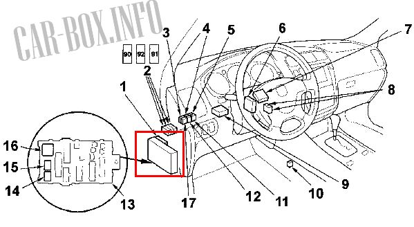
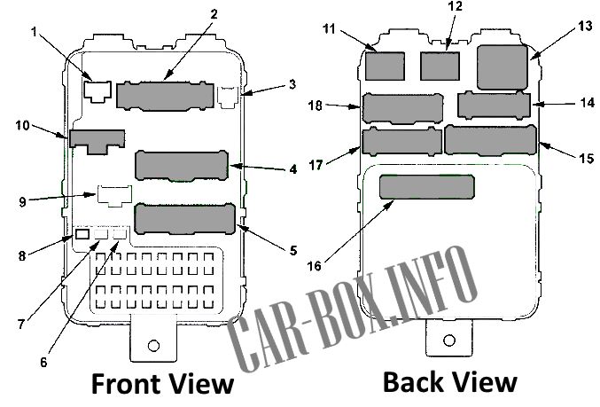
Control Unit Component Layout: 1 – Driver-side multiplex control unit, 2 – Auxiliary fuse holders, 3 – Moonroof close relay, 4 – Fog light relay, 5 – Audio system rear amplifier relay (2003–2004 models with BOSE audio), 6 – Automatic lighting control unit, 7 – Daytime running lights (DRL) control unit (Canada models), 8 – PGM-FI main relays #1 and #2, 9 – Tire Pressure Monitoring System (TPMS) module (2004–2008 models), 10 – Rear heater blower motor relay, 11 – Heated seat relay, 12 – Parking light relay, 13 – Under-dash driver-side fuse panel, 17 – Moonroof open relay
Under-Dash Fuse Panel
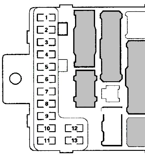
Labeled #13 in the diagram above.

Panel View
| Diagram | ||
|---|---|---|
|
||
| No. | Circuit Protected | Rating (A) |
| 1 | Honda Pilot fuel pump fuse, Supplemental Restraint System (SRS) unit (VA) | 15 |
| 2 | Supplemental Restraint System (SRS) control unit | 10 |
| 3 | A/C compressor clutch relay, blower motor relay, A/C control panel, A/C control unit, condenser fan motor relay, fan cut-off relay, rear heater blower motor relay, HVAC rear control unit, mode control motor (rear), rear window defogger relay, recirculation control switch | 7.5 |
| 4 | Power mirrors, automatic lighting control unit, compass module (models without navigation), option connector "R", auto-dimming side mirrors, heated mirrors, heated seat relay | 7.5 |
| 5 | Daytime Running Lights (DRL) control unit (Canada models) | 10 |
| 6 | Powertrain Control Module (PCM), VTM-4 relay | 15 |
| 7 | OPDS (Occupant Detection System) module, passenger seat position sensor | 7.5 |
| 8 | Accessory power socket relay, auxiliary connectors, shift lock solenoid valve | 7.5 |
| 9 | Daytime running lights module, brake light switch, cruise control main switch indicator, driver-side multiplex control unit, driver seat position control module, gauge cluster, power door lock relay, keyless entry receiver module, passenger-side multiplex control unit, side airbag indicator, rain sensor module (models with automatic wipers), backup light relay, Variable Torque Management 4WD (VTM-4) module, VTM-4 lock switch, windshield washer motor (models with automatic wipers), TPMS receiver module (2004–2008 models) | 10 |
| 10 | Turn signal/hazard flasher relay | 7.5 |
| 11 | Rear window wiper intermittent control module, rear window wiper motor, rear window washer motor | 10 |
| 12 | Windshield wiper intermittent relay, windshield washer motor, windshield wiper motor (models with automatic wipers), automatic wiper control module (models with automatic wipers) | 30 |
| 13 | Not used | — |
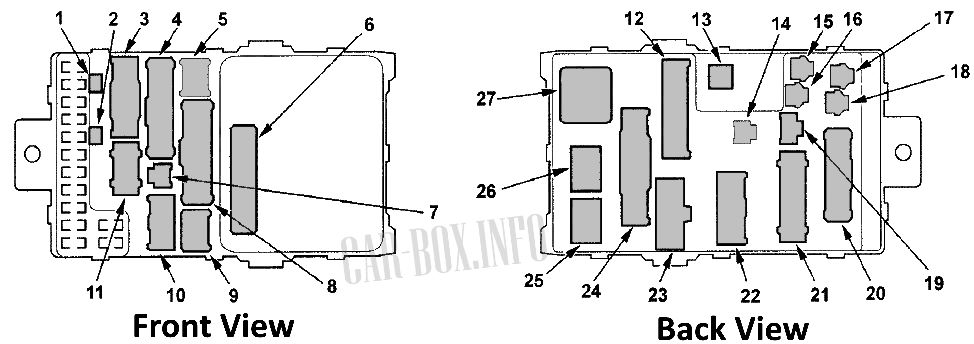
| Relays | ||
|
||
| 22 | Ignition switch harness connector | |
| 13 | SRS main harness connector | |
| 1 | Diode: Driver door courtesy light | |
| 2 | Diode: Left rear door courtesy light | |
| 6 | Connector "A" – Driver-side multiplex control unit | |
| 26 | Backup light relay | |
| 25 | Starter cut relay | |
| 27 | Turn signal / hazard flasher relay | |
| 7 | SCS (Service Check Connector) / DLC maintenance connector | |
| Unlisted: Wiring harness connectors or unused slots | ||
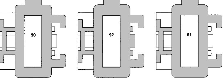
Auxiliary Fuse Holders
Labeled #2 in the diagram above.
| Diagram | ||
|---|---|---|
|
||
| No. | Circuit Protected | Rating (A) |
| 90 |
|
7.5 |
| 91 |
|
|
| 92 |
|
|
Passenger-Side Location

Control Unit Component Layout: 18 – Shift lock solenoid relay, 19 – Throttle actuator control module relay, 20 – Air-fuel ratio (A/F) sensor relay, 21 – Audio system amplifier (2004–2008 models with BOSE audio), 22 – Climate control ECU, 23 – Keyless entry receiver unit, 24 – Rear window defogger relay, 25 – Under-dash passenger-side fuse panel, 26 – Passenger-side multiplex control unit, 27 – Power window relay, 28 – Accessory power socket relay, 29 – SRS control unit, 30 – Front audio amplifier (2003–2004 models), 31 – Ignition coil relay.
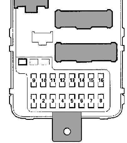
Under-Dash Fuse Panel
Labeled #25 in the diagram above.
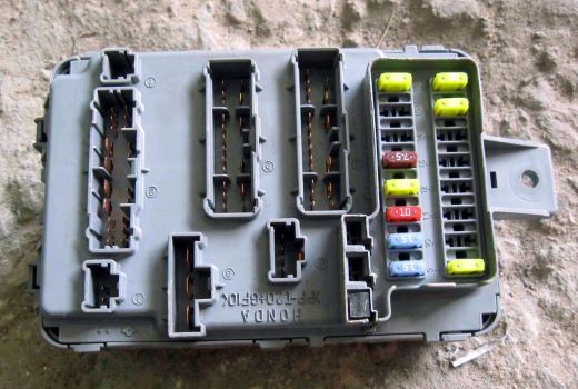
Panel View
| Diagram | ||
|---|---|---|
|
||
| No. | Circuit Protected | Rating (A) |
| 1 | Power moonroof | 30 |
| 2 | Power driver seat rear height adjustment motor, driver seat backrest recline motor, driver seat position control unit | 20 |
| 3 | Power passenger seat front height adjustment motor, power passenger seat slide motor | 20 |
| 4 | Power driver seat front height adjustment motor, power driver seat slide motor, driver seat position control unit | 20 |
| 5 | Power passenger seat rear height adjustment motor, power passenger seat backrest recline motor, passenger-side multiplex control unit | 20 |
| 6 | Daytime Running Lights (DRL) control unit (Canada models) | 10 |
| 7 | Left rear power window, moonroof relay (2003–2004 models), moonroof close relay (2003–2004 models) | 20 |
| 8 | Front passenger power window | 20 |
| 9 | Audio unit, front accessory power socket, DVD player (models with rear entertainment system), cellular phone auxiliary jack (models with rear entertainment system), sub-display (models without navigation), navigation unit, navigation display, Honda Pilot cigarette lighter fuse, rear entertainment control panel and display (models with RES), rearview camera control module (models with navigation) | 15 |
| 10 | Shift lever position indicator illumination, audio unit illumination, climate control illumination, cruise control switch illumination, instrument panel dimmer switch illumination, seat memory switch illumination, driver-side multiplex control unit, RES DVD unit, glove box light, fog light switch illumination, gauge cluster backlighting, hazard switch illumination, interior light switch illumination, front parking lights, left side marker light, license plate lights, moonroof switch illumination, sub-display illumination, navigation unit backlighting, navigation control module, option connector "T", passenger airbag off indicator, right front side marker light, seat heater switch illumination, parking light relay, trailer harness connector, VTM-4 lock switch illumination, interior lights (2004–2008 models) | 15 |
| 11 | Cargo area light, door courtesy lights, sub-display (models without navigation), navigation control module, vanity mirror lights, front and rear map lights, footwell lights (2004–2008 models), TPMS receiver unit (2004–2008 models) | 10 |
| 12 | Passenger-side multiplex control unit | 20 |
| 13 | Automatic lighting control unit, driver door multiplex control unit, driver seat position module, driver-side multiplex control unit, seat memory indicator, gauge cluster, immobilizer module, immobilizer indicator light, keyless entry receiver, navigation control unit, passenger-side multiplex control unit, rearview camera control module (models with navigation), security system indicator | 7.5 |
| 14 | Heated seats | 20 |
| 15 | Driver door multiplex control unit, power window master module, moonroof open relay (2004–2008 models), moonroof close relay (2004–2008 models) | 7.5 |
| 16 | Right rear power window | 20 |
| Relays | ||
|
||
| 12 | Accessory power outlet relay | |
| 6 | A/C compressor clutch relay | |
| 7 | Right rear door courtesy light diode | |
| 8 | Front passenger door courtesy light diode | |
| 16 | Connector "A" – Passenger-side multiplex control unit | |
| 11 | Power window relay | |
| 13 | Rear window defogger relay | |
| Unlisted: Wiring harness connectors or unused slots | ||
Engine Compartment Fuse Boxes
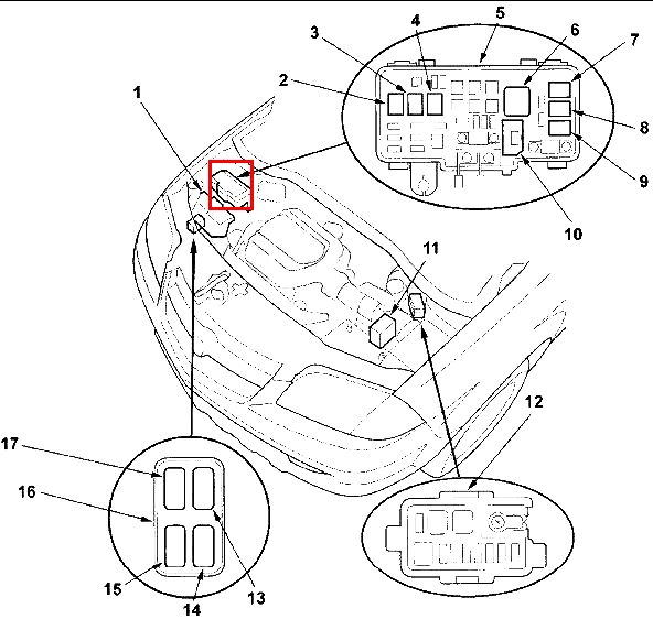
Engine Compartment Component & Fuse Box Layout
- 1 – Powertrain Control Module (PCM),
- 2–10 – Relays in primary fuse box,
- 11 – Vehicle Stability Assist (VSA) control unit,
- 12 – Auxiliary fuse box,
- 16 – Auxiliary relay box.
Primary Under-Hood Fuse Box
Labeled #2–10 in the diagram above.
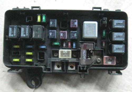
Box View
| Diagram | ||
|---|---|---|
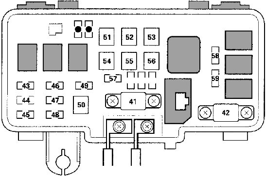
|
||
| No. | Circuit Protected | Rating (A) |
| 41 | Primary battery feed, main electrical system supply | 120 |
| 42 | Ignition switch (BAT feed), option connector "U" | 50 |
| 43 | Daytime Running Lights (DRL) module (Canada models), right headlight, fog light relay | 20 |
| 44 | Not used | — |
| 45 | Daytime Running Lights (DRL) module (Canada models), headlight switch relay, left headlight, high beam indicator | 20 |
| 46 | Data Link Connector (DLC / OBD-II port), fuel injectors, PGM-FI main relay #1, camshaft position (CMP) sensor, crankshaft position (CKP) sensor A, crankshaft position (CKP) sensor B | 15 |
| 47 | Brake lights, driver-side multiplex control unit, high-tone horn, ignition switch, auxiliary fuse #90, Powertrain Control Module (PCM), trailer socket feed, Vehicle Stability Assist (VSA) module | 20 |
| 48 | Audio system (models without RES), front audio amplifier (2003–2004 models), rear audio amplifier (2003–2004 models), audio power amplifier (2004–2008 models) | 20 |
| 49 | Hazard warning lights | 15 |
| 50 | Front fog lights | 20 |
| 51 | Under-dash passenger-side fuses #1, 7, 8, 15, 16; power window relay | 40 |
| 52 | Rear heater blower motor | 30 |
| 53 | Rear window defogger grid | 30 |
| 54 | Under-dash passenger-side fuses #9, 10, 11, 12, and 13 | 40 |
| 55 | Under-dash passenger-side fuses #2, 3, 4, 5, 6, and 14 | 40 |
| 56 | HVAC blower motor relay | 40 |
| 57 | Radiator cooling fan motor | 30 |
| 58 | A/C condenser fan motor | 30 |
| 59 | A/C compressor clutch magnetic coil | 7.5 |
| Relays | ||

|
||
| 8 | A/C compressor clutch relay | |
| 5 | Blower motor relay | |
| 6 | Condenser fan relay | |
| 3 | Diode | |
| 9 | Battery load detector module | |
| 4 | Horn relay | |
| 1 | Headlight relay #1 | |
| 2 | Headlight relay #2 | |
| 7 | Radiator cooling fan relay | |
| Unlisted: Wiring harness connectors or unused slots | ||
Auxiliary Under-Hood Fuse Box
Labeled #12 in the diagram above.

Box View
| Diagram | ||
|---|---|---|
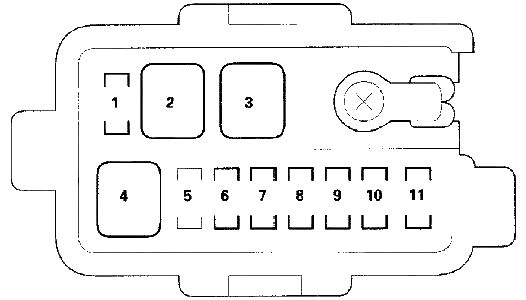
|
||
| No. | Circuit Protected | Rating (A) |
| 1 |
|
20 |
| 2 | Vehicle Stability Assist (VSA) control module (+B FSR) | 40 |
| 3 | Vehicle Stability Assist (VSA) control module (+B MTR) | 30 |
| 4 |
|
20 |
| 5 | Not used | — |
| 6 | Rear accessory power socket | 20 |
| 7 | Throttle Actuator Control (TAC) module | 15 |
| 8 | Ignition coils | 15 |
| 9 | Air-fuel ratio (A/F) sensors (Bank 1, Bank 2), A/F sensor relay, cooling fan motor relay, active control engine mount solenoid valve, EVAP canister purge solenoid valve, secondary heated oxygen sensors (HO2S - Bank 1, Bank 2), battery load detector (2004–2008 models) | 15 |
| 10 | Powertrain Control Module (PCM) | 7.5 |
| 11 | Power window control module | 20 |
| Footnotes: *1 – 2003–2004 models; *2 – 2005–2008 models | ||
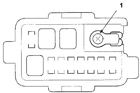
|
||
| 1 | T5 starter harness connector | |
