3 is a compact car produced by Mazda Motor Corporation in Japan. In the manufacturer's home country, it is called Axela. Mazda 3 was introduced in 2003 as the successor series to the Familia (323 or - export names). In this article, we will take a detailed look at the fuse box diagrams for the Mazda 3 (second generation; codename BL) 2009, 2010, 2011, 2012, 2013 years of manufacture.

Here you will find the locations and photos of distribution boxes. The fuses responsible for the “Cigarette lighter” and “Fuel Pump” are highlighted in bold.
In the engine compartment
There are 3 fuse boxes and relays located here.
Main fuse box

The main distribution box in the engine compartment is located on the left side between the battery and the left fender (shown by the arrow).
1. Press the catch on the plastic protective cover of the mounting side and remove it.

General view.
| Diagram | ||
|---|---|---|

|
||
| No. | Description | Amps |
| F1 | Engine cooling fan motor | 40 |
| F2 | Engine control unit - ENG MAIN | 40 |
| F3 | Protection of various electrical circuits - BTN 1 | 50 |
| F4 | Air conditioner | 7.5 |
| F5 | High beam bulbs in the headlight clusters | 20 |
| F6 | Fog lamp bulbs | 15 |
| F7 | Headlight washer | 20 |
| F8 | Ventilation hatch | 15 |
| F9 | Right windshield heater element | 40 |
| F10 | Left windshield heater element | 40 |
| F11 | Engine cooling fan motor | 40 |
| F12 | Interior lamps | 15 |
| F13 | Traction control unit | 15 |
| F14 | DSC anti skid control unit | 20 |
| F15 | Protection of various electrical circuits - BTN 2 | 7.5 |
| F17 | Heating and ventilation fan electric motor | 40 |
| F19 | Rear window heater element | 30 |
| F20 | Ignition switch - IG KEY 2 | 40 |
| F21 | Ignition switch - IG KEY 1 | 40 |
| F22 | Horn | 15 |
| F23 | Brake lamps | 15 |
| F24 | Engine control unit - ENG+B | 10 |
| F25 | Fuel pump fuse | 25 |
| F26 | ABS control unit (ABS system) | 40 |
| F27 | Front seat heating element | 20 |
| F28 | Electrohydraulic power steering control unit | 80 |
| F30 | ABS IG control unit | 10 |
| F32 | Dipped beam bulb in the right headlight unit | 15 |
| F33 | Dipped beam bulb in the left headlight unit | 15 |
| F34 | Instrument cluster illumination lamps | 7.5 |
| F35 | Parking light bulbs in taillights | 15 |
| F36 | Engine management system - ENG ING | 15 |
| F37 | Engine control unit - ENG BAR 1 | 15 |
| F38 | Engine control unit - ENG BAR 2 | 20 |
| F39 | ETV throttle valve actuator | 15 |
| Purpose of relay modules in the block | |

|
|
| R1 | Fuel injectors (L3 / TC) |
| R2 | dipped headlights |
| R3 |
|
| R4 | Headlight relay - high beam |
| R5 | Fuel pump relay |
| R6 | Daytime Running Lights |
| R7 | Starter |
| R8 | Blower relay |
| R9 | Horn relay |
| R10 | TNS / marker lamps |
| R11 | Rear window heater |
| R12 | Air conditioner |
| R13 | Main relay |
Power board on battery

A separate board of "power" elements is installed on the "plus" terminal of the battery.
1. Unclip the two latches of the plastic protective cover of the battery cover and remove it.
2. Use a ring wrench or a "10" head to loosen the nut tightening bolt of the wire terminal on the "minus" terminal of the battery, take the wire aside.
3. With a head "on 8" unscrew two nuts fastening the wire lugs to the fuse.
| Location of the "power" fuses on the battery | ||
|---|---|---|

|
||
| No. | Description | Amps |
| F1 | Alternator | 100 |
| F2 | No | - |
| Diagram of the relay and fuse box on the battery | ||
|---|---|---|

|
||
| No. | Decoding | Amps |
| F1 | Engine cooling fan motor | 30 |
| F2 | 30 | |
| 1 | overparking light relay | |
| 2 | small relay | |
Additional elements
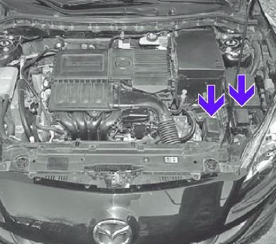
Two additional blocks are located in the engine compartment on the left side (shown by arrows)
Since the covers on the additional relay blocks are the same and the inscriptions on the relay and fuse assignments are duplicated, the specific purpose of a particular element can only be known experimentally.
In the passenger compartment
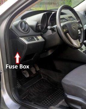
The distribution box is located to the left of the steering column at the end of the instrument panel. Remove the trim to gain access.
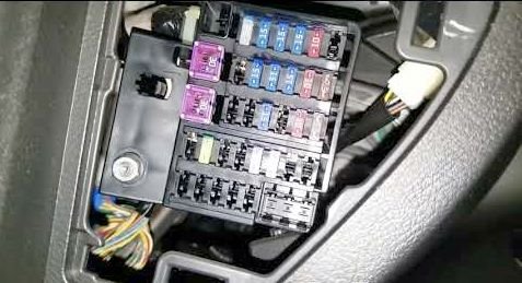
Access example.
| Diagram | ||
|---|---|---|

|
||
| No. | Decoding | Amps |
| F1 | Radio recorder | 30 |
| F2 | Engine cooling system | 30 |
| F3 | Power window gear motors | 50 |
| F4 | central lock | 7.5 |
| F5 | Not used | - |
| F6 | - | |
| F7 | Electric steering wheel lock | 15 |
| F8 | Airbag system | 15 |
| F9 | Not used | - |
| F10 | Alarm | 15 |
| F11 | Protection of various electrical circuits - METER | 15 |
| F12 | Electrical outlets | 15 |
| F13 | Rear door window wiper | 15 |
| F14 | Mazda 3 bl cigarette lighter fuse | 20 |
| F15 | Not used | - |
| F16 | Heating and ventilation fan electric motor | 10 |
| F17 | External rear view mirror gearmotors | 10 |
| F18 | Starter signal | 10 |
| F19 | Not used | - |
| F20 | Audio system | 7.5 |
| F21 | Heated exterior mirror elements | 7.5 |
| F22 | Side lighting system for turning | 7.5 |
| F23 | Not used | - |
| F24 | Engine control unit | 10 |
| F25 | Not used | - |
| F26 | - | |
| F27 | - | |
| F28 | - | |
| F29 | - | |
| F30 | Power window gearmotors | 25 |
| F31 | Not used | - |
| F32 | Windshield wiper and washer | 25 |
| F33 | Not used | - |
| F34 | - | |
