
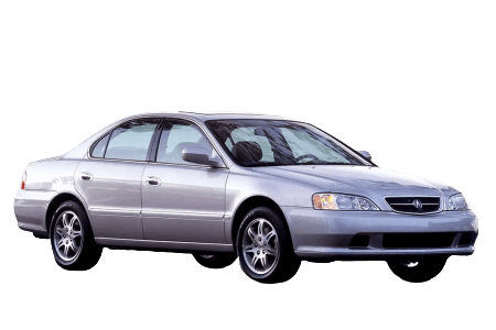
In this article, we will take a detailed look at the fuse diagrams for the second-generation Acura TL (UA4/UA5): 1998, 1999, 2000, 2001, 2002, and 2003 model years.
Fuse No. 9 in the passenger’s side interior fuse box is responsible for the cigarette lighter.
Engine Compartment
General arrangement of the electronic control units in the engine compartment of the Acura TL.

|
|
| 1 | Relay Box No. 1 (1998–2001) |
| 2 | Under-Hood Fuse Box |
| 3 | Relay Box No. 2 |
| 4 | Intermittent Wiper Relay |
| 5 | Relay Box No. 3 (2002–2003) |
Under-Hood Fuse Box
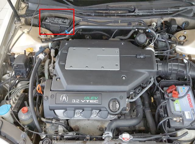
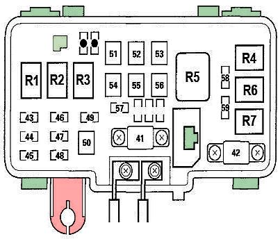
Located on the passenger’s side, at the rear of the engine compartment.
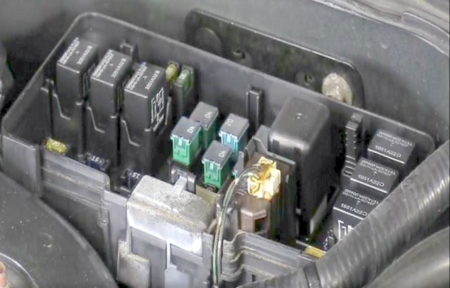
To access the fuses, depress the retaining tabs.
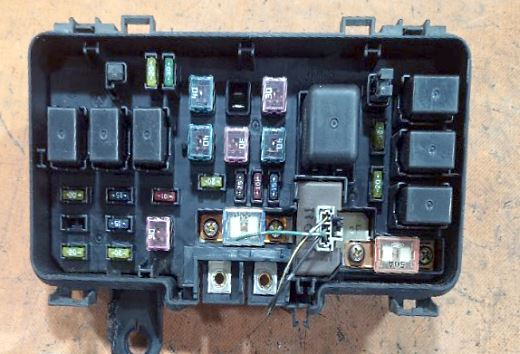
General view of the under-hood fuse box.
| Diagram | ||
|---|---|---|
|
||
| No. | Description | Amps |
| R1 | Headlight Relay No. 1 | - |
| R2 | Headlight Relay No. 2 | - |
| R3 | Horn Relay | - |
| R4 | A/C Condenser Fan Relay | - |
| R5 | Blower Motor Relay | - |
| R6 | Radiator Fan Relay | - |
| R7 | A/C Compressor Clutch Relay | - |
| 41 | Alternator, Battery, Power Distribution | 120 A |
| 42 | Ignition Switch (BAT) | 60 A |
| 43 | Right Headlight, Daytime Running Lights (DRL) | 20 A |
| 44 | Not Used | - |
| 45 | Left Headlight, Combination Light Switch (2002–2003), Daytime Running Lights (DRL) Unit, DRL Diode, Gauge Assembly, High Beam Cut Relay (DRL) | 20 A |
| 46 | Data Link Connector (DLC), PGM-FI Main Relay | 15 A |
| 47 | Brake Pedal Position Switch, Horn Relay, Ignition Key Switch/Key Light, Security Horn Relay (1999) | 20 A |
| 48 |
|
20 A |
| 49 | Hazard Warning Switch | 15 A |
| 50 | 1998–2001: ABS Pump Motor Relay | 30 A |
| Type S Only: VSA Throttle Motor Relay | 20 A | |
| 51 | Power Window Motor, Power Window Relay | 40 A |
| 52 | 1998–2001: TCS Fail-Safe Relay | 20 A |
| 2002–2003: Fog Light Relay | ||
| 53 | Rear Window Defogger Relay | 40 A |
| 54 | Interior Fuse Box No. 2: Fuses 9, 10, 11, 12, 13 | 40 A |
| 55 | Interior Fuse Box No. 1: Fuses 2, 3, 4, 5, 6 | 40 A |
| 56 | Blower Motor Relay | 40 A |
| 57 | Except Type S: Radiator Fan Relay | 20 A |
| Type S Only: Radiator Fan Relay | 30 A | |
| 58 | Except Type S: A/C Compressor Clutch Relay, A/C Condenser Fan Relay, Radiator Fan Control Module (1998–2001) | 20 A |
| Type S Only: A/C Compressor Clutch Relay, A/C Condenser Fan Relay, Radiator Fan Control Module (1998–2001) | 30 A | |
| 59 | Taillight Relay | 15 A |
Additional Relay Boxes

There are three additional relay boxes located in the engine compartment.
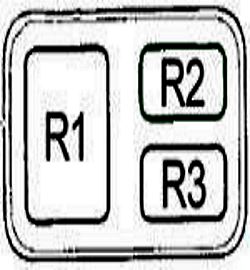
| Relay Box No. 1 (1998–2001) | |
|
|
| R1 | ABS Pump Motor Relay |
| R2 | ABS/TCS Fail-Safe Relay |
| R3 | TCS Relay |
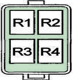
| Relay Box No. 2 | |
|
|
| R1 | Shift Lock Solenoid Relay |
| R2 | 2002–2003: Taillight Relay |
| R3 | 2002–2003: Seat Heater Relay |
| 1998–2001: Security Horn Relay | |
| R4 | 2002–2003: High Beam Cut Relay (DRL) |
| 1998–2001: Seat Heater Relay | |
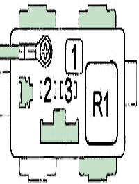
| Relay Box No. 3 (2002–2003) | |
|
|
| R1 | ABS Pump Motor Relay |
| 1 | ABS Motor 40 A |
| 2 | ABS Fail-Safe 20 A |
| 3 | ABS Motor Check 7.5 A |
Passenger Compartment
General arrangement of the electronic control units in the passenger compartment of the Acura TL.
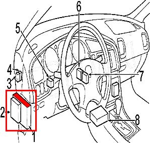
|
|
| 1 | Driver’s Side Interior Fuse Box |
| 2 | Driver’s Multiplex Control Unit (MCU) |
| 3 | Moonroof Close Relay |
| 4 | Moonroof Open Relay |
| 5 | PGM-FI Main Relay |
| 6 | Cruise Control Module |
| 7 | DRL Control Unit |
| 8 | Supplemental Restraint System (SRS) Module |
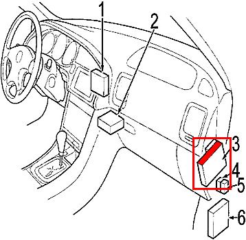
|
|
| 1 | BOSE Equalizer |
| 2 | Powertrain Control Module (PCM) |
| 3 | Passenger’s Side Interior Fuse Box |
| 4 | Navigation Relay |
| High Beam Cut Relay (With DRL System (1998–2001)) | |
| 5 | 1998–2001: Taillight Relay |
| 2002–2003: Navigation Relay | |
| 6 | ABS/TCS Control Module |
Driver’s Side Interior Fuse Box
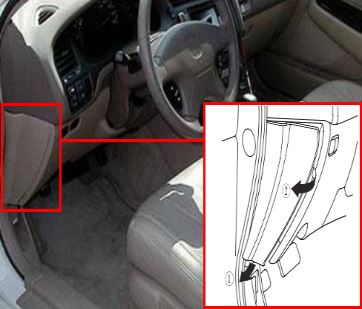
Interior Fuse Box No. 1 is located on the driver’s side of the dashboard.
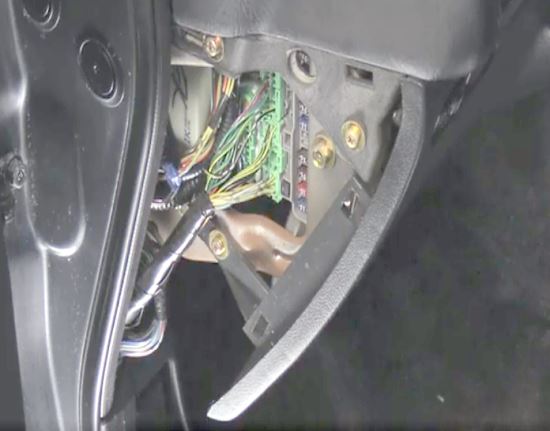
To access the fuses, pull the bottom of the cover, then disengage it from its hinges by pulling it toward you.
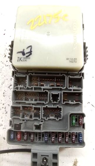
General view of the front of the fuse box.
| Diagram | ||
|---|---|---|
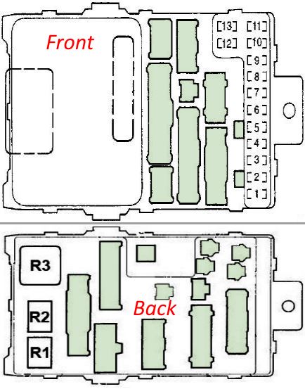
|
||
| No. | Description | Amps |
| R1 | Starter Cut Relay | - |
| R2 | Reverse Relay | - |
| R3 | Turn Signal/Hazard Relay | - |
| 1 | PGM-FI Main Relay, Supplemental Restraint System (SRS), Fuel Pump Fuse | 15 A |
| 2 | Supplemental Restraint System (SRS) | 10 A |
| 3 | HVAC, Radiator Fan Control Module, Rear Window Defogger Relay, Fan Control Relay (Type S) | 7.5 A |
| 4 | ABS/TCS Control Module (Except Type S), Power Mirror Defoggers, Power Mirrors, Option Connector S, Seat Heater Relay, VSA Control Module (Type S) | 7.5 A |
| 5 | Daytime Running Lights (DRL) System | 7.5 A |
| 6 | Charging System, Cruise Control, Electrical Load Detector (ELD) Unit, Engine Mount Control System, Evaporative Emission Control System, PCM (VBSOL), Primary and Secondary Heated Oxygen Sensor (HO2S), Radiator Fan Control Module, VSP Sensor (1999 With Navigation), Cruise Control/TCS Switch (Except Type S) or Cruise Control/VSA Off Switch (Type S) Indicator Light, Intake Manifold Runner Control (IMRC) Module (Type S), VSA Control Unit (Type S) | 15 A |
| 7 | Occupant Position Detection System (OPDS) Unit (2000–2002), Shift Lock Relay (1999), Wiper/Washer (1999) | 7.5 A |
| 8 | Accessory Power Socket Relay, Navigation System, Option Connector R, Shift Lock Solenoid | 7.5 A |
| 9 | Automatic Dimming Inside Mirror, Brake Light Failure Sensor, Clock (Without Navigation), Driver’s and Passenger’s Multiplex Control Units (MCU), Daytime Running Lights Indicator, Gauge Assembly, Reverse Relay, Shift Lock Relay (2000–2002) | 7.5 A |
| 10 | Turn Signal/Hazard Relay | 7.5 A |
| 11 | Ignition Coils | 15 A |
| 12 | Wiper/Washer | 30 A |
| 13 | Starter Signal, PGM-FI Main Relay, Powertrain Control Module (PCM) | 7.5 A |
Passenger’s Side Interior Fuse Box
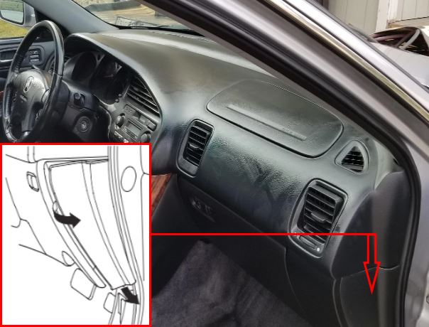
Interior Fuse Box No. 2 is located on the passenger’s side of the dashboard.
| Diagram | ||
|---|---|---|
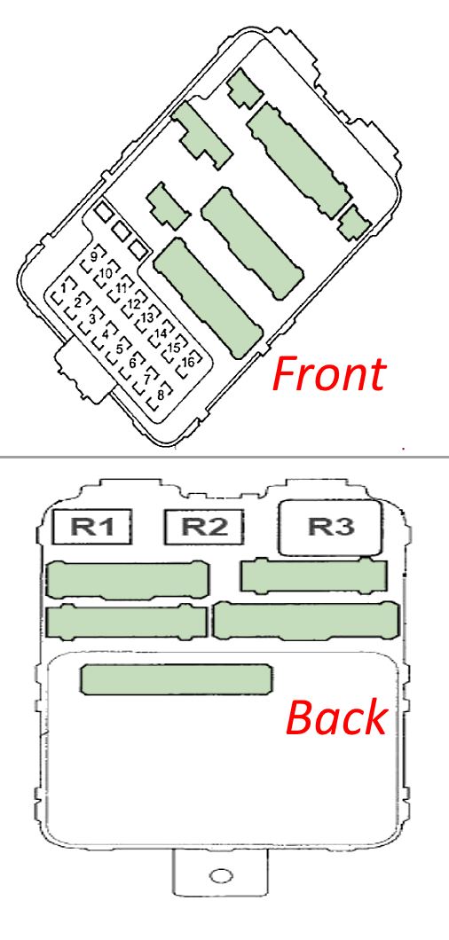
|
||
| No. | Description | Amps |
| R1 | Power Window Relay | - |
| R2 | Accessory Power Socket Relay | - |
| R3 | Rear Window Defogger Relay | - |
| 1 | 1998–2001: Moonroof Close and Open Relays | 30 A |
| 2002–2003: Power Window (Driver’s Side) | 20 A | |
| 2 | 1998–2001: Driver’s Power Seat Adjustment Switch (Reclining) | 20 A |
| 2002–2003: Power Seat Control Unit (Reclining) | 20 A | |
| 3 | Seat Heater Relay | 20 A |
| 4 | 1998–2001: Driver’s Power Seat Adjustment Switch (Slide) | 20 A |
| 2002–2003: Power Seat Control Unit (Slide) | 20 A | |
| 5 | Front Passenger’s Power Seat Adjustment Switch (Slide), Passenger’s Multiplex Control Unit (MCU) | 20 A |
| 6 | Front Passenger’s Power Seat Adjustment Switch (Reclining) | 20 A |
| 7 | Left Rear Power Window Switch, Door Multiplex Control Unit (2002–2003), Moonroof Close and Open Relays, Power Window Control Unit (2002–2003) | 20 A |
| 8 | Front Passenger’s Power Window Switch | 20 A |
| 9 | Acura TL Cigarette Lighter Fuse, Accessory 12 V Socket Relay, Audio System, Front Accessory 12 V Socket, Rear Accessory 12 V Socket, Stereo Amplifier | 20 A |
| 10 | Daytime Running Lights (DRL) Unit, Navigation Display, Navigation Relay (1999), Navigation System | 10 A |
| 11 | Ceiling Light, Driver’s and Front Passenger’s Door Courtesy Lights, Passenger’s Multiplex Control Unit (MCU), Trunk Lid Opener Main, Power Seat Control Unit (2002–2003), Spotlights, Trunk Light | 7.5 A |
| 12 | Power Door Locks, Passenger’s Multiplex Control Unit (MCU), Trunk Lid Opener Main | 20 A |
| 13 | Climate Control, Clock (Except Navigation), Driver’s, Door, and Passenger’s Multiplex Control Units (MCU), Driving Position Memory Switch (2002–2003), Gauge Assembly, Keyless Receiver Unit (2002–2003), PCM (VBU), Radiator Fan Control Unit (2002–2003), Security Indicator | 7.5 A |
| 14 | Except Type S: ABS/TCS System | 7.5 A |
| Type S Only: A/C Compressor | 7.5 A | |
| 15 | 1998–2001: Door Multiplex Control Unit (Driver’s Power Window) | 20 A |
| 2002–2003: Moonroof Close and Open Relays | 30 A | |
| 16 | Right Rear Power Window Switch | 20 A |
