Opel / Vauxhall Mokka is a mini crossover, shown for the first time at the Geneva Motor Show 2012. In the company's car line-up it occupies a place below the Antara. It is built on the GM Gamma II platform. In this article we will understand in detail fuse box diagrams Opel / Vauxhall Mokka (first generation) 2012, 2013, 2014, 2015, 2016, 2017, 2018, 2019, 2020 years of manufacture.
Here you will find the locations and photos of the mounting blocks. Also, we will separately mark the fuses responsible for the cigarette lighter and the fuel pump.
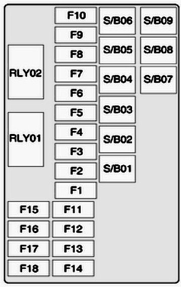
In the luggage compartment

The mounting block is located in the left side of the boot behind the plastic cover.

General view.
| Diagram | |
|---|---|
|
|
| Models 2017 - 2020 | |
| No. | Description |
| S/B01 | Not used |
| S/B02 | Not used |
| S/B03 | Not used |
| S/B04 | AC/DC Inverter Module |
| S/B05 | Not used |
| S/B06 | Not used |
| S/B07 | DC transformer 400 W |
| S/B08 | DC transformer 400 W |
| S/B09 | Not used |
| RLY01 | Right turn signal lamp |
| RLY02 | Left turn signal lamp |
| F1 | Not used |
| F2 | Not used |
| F3 | Amplifier |
| F4 | Not used |
| F5 | Rear-wheel drive control module |
| F6 | Left turn signal lamp |
| F7 | Right turn signal lamp |
| F8 | Not used |
| F9 | Not used |
| F10 | Not used |
| F11 | Not used |
| F12 | Not used |
| F13 | Not used |
| F14 | Not used |
| F15 | Not used |
| F16 | Not used |
| F17 | Not used |
| F18 | Not used |
| Models 2012 - 2016 | |
| No. | Description |
| S/B01 | Electric driver's seat adjustment / memory module |
| S/B02 | Electric adjustment of the passenger seat |
| S/B03 | trailer module |
| S/B04 | Inverter / Voltage Converter |
| S/B05 | battery |
| S/B06 | headlight washer |
| S/B07 | Reserve |
| S/B08 | |
| S/B09 | |
| RLY01 | Ignition relay |
| RLY02 | Start relay |
| F1 | Driver's seat lumbar support |
| F2 | Passenger seat lumbar support |
| F3 | Amplifier |
| F4 | Trailer Wiring Harness Connector |
| F5 | Permanent all-wheel drive system |
| F6 | Indication |
| F7 | Spare |
| F8 | Trailer |
| F9 | Spare |
| 10 | |
| F11 | Trailer |
| F12 | Navigation system |
| F13 | Heated steering wheel |
| F14 | Trailer Wiring Harness Connector |
| F15 | Steering wheel |
| F16 | Water-in-fuel sensor |
| F17 | Interior mirror |
| F18 | Spare |
In the passenger compartment
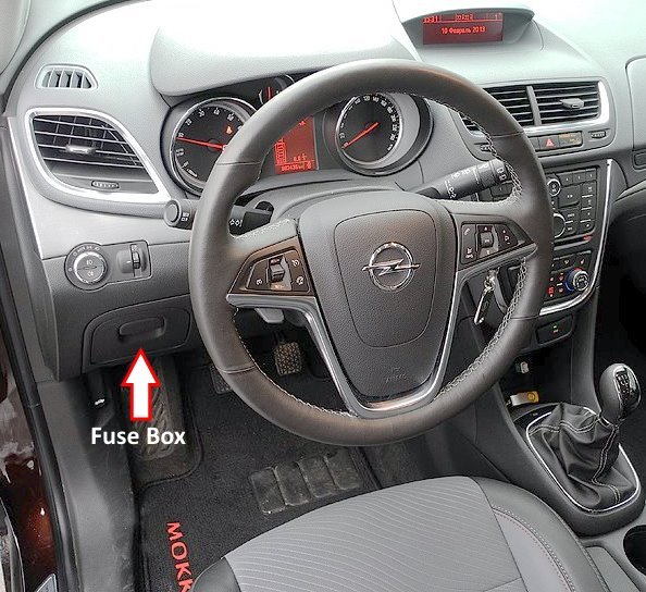
The mounting block is located on the driver's side under the instrument panel. To get to its elements, you need to remove the glove compartment.

General view of the Opel / Vauxhall Mokka interior fuse box.
| Diagram | |
|---|---|

|
|
| Models 2017 - 2020 | |
| No. | Description |
| CB1 | Not used |
| RLY01 | auxiliary relay |
| RLY02 | Backdoor |
| RLY03 | Not used |
| RLY04 | Not used |
| RLY05 | Logistics mode |
| F1 | Body equipment control unit 1 |
| F2 | Body equipment control unit 2 |
| F3 | Body equipment control unit 3 |
| F4 | Body equipment control unit 4 |
| F5 | Body equipment control unit 5 |
| F6 | Body equipment control unit 6 |
| F7 | Body equipment control unit 7 |
| F8 | Body equipment control unit 8 |
| F9 | Discrete logic ignition switch |
| F10 | Diagnostic module battery sensor |
| F11 | Data link connector |
| F12 | HVAC / ICS module |
| F13 | Rear door relay |
| F14 | Central Gateway Module |
| F15 | Lane departure warning / GENTEX |
| F16 | Adaptive front lighting module |
| F17 | Electric steering column lock |
| F18 | Parking Assist Module / Side Blind Zone Warning |
| F19 | Body Control Module / Variable Voltage Control |
| F20 | Clock spring |
| F21 | Air conditioning / Auxiliary Power Outlet / PRNDL |
| F22 | Auxiliary Power Outlet / DC Center |
| F23 | HVAC / ICS module |
| F24 | Not used |
| F25 | OnStar system |
| F26 | Heated steering wheel |
| F27 | Instrument cluster/auxiliary heater/auxiliary virtual image display |
| F28 | Trailer 2 |
| F29 | Infotainment system |
| F30 | DC/DC 400W |
| F31 | Instrument Cluster Module Battery |
| F32 | Silver Box Audio Module/Navigation |
| F33 | Trailer 1 |
| F34 | Passive entry / passive start |
| M01 | Positive temperature coefficient |
| S/B01 | Electrically operated passenger seat |
| S/B02 | Not used |
| S/B03 | Front power windows |
| S/B04 | Rear power windows |
| S/B05 | Logistic mode relay |
| S/B06 | Power driver's seat |
| S/B07 | Not used |
| S/B08 | Trailer Interface Module |
| Models 2012 - 2016 | |
| No. | Description |
| M01 | PTC |
| S/B01 | Reserve |
| S/B02 | |
| S/B03 | Front power window motor |
| S/B04 | Rear power window motor |
| S/B05 | Logistic mode relay |
| S/B06 | Reserve |
| S/B07 | |
| S/B08 | |
| CB1 | |
| RLY01 | Accessory relay |
| RLY02 | Doors |
| RLY03 | Spare |
| RLY04 | Spare |
| RLY05 | Logistics mode |
| F1 | Body control unit |
| F2 | |
| F3 | |
| F4 | |
| F5 | |
| F6 | |
| F7 | |
| F8 | |
| F9 | Ignition lock |
| F10 | Safety Diagnostic Module |
| F11 | Data Connector, Door Locks |
| F12 | Heating, ventilation and air conditioning MDL/ICS |
| F13 | Rear doors |
| F14 | Parking assistance system |
| F15 | Lane Departure Warning, Interior Mirror |
| F16 | Adaptive front lighting module |
| F17 | Power window, driver's side |
| F18 | Rain sensor |
| F19 | Body Control Module |
| F20 | Illuminated switch on the steering wheel |
| F21 | Transmission control unit |
| F22 | Opel / Vauxhall Mokka cigarette lighter fuse (power outlet) |
| F23 | Reserve |
| F24 | |
| F25 | |
| F26 | Automated passenger detection system |
| F27 | Instrument cluster |
| F28 | Headlight switch / AFL / DC converter |
| F29 | Reserve |
| F30 | Reserve |
| 2015 - 2016: Transmission control module battery | |
| F31 | IPC Battery, Instrument Cluster |
| F32 | Radio / Telephone / Aux Jack |
| F33 | Display, infotainment system |
| F34 | OnStar / UHP / DAB |
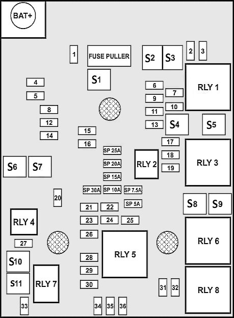
In the engine compartment

The unit is located next to the battery behind the plastic cover.

General view.
| Diagram | |
|---|---|
|
|
| Models 2017 - 2020 | |
| No. | Description |
| 1 | Sunroof |
| 2 | Exterior rear-view mirror switch/Driver's side power window/ Rain sensor/Universal garage door opener |
| 3 | Crankcase ventilation valve |
| 4 | Not used |
| 5 | Electronic brake control module valve |
| 6 | Smart battery sensor |
| 7 | Electric steering column lock |
| 8 | Transmission Control Module / FICM |
| 9 | Automatic presence detection module |
| 10 | Headlight correction switch / Headlight correction motor / Rear view camera / Interior rear view mirror |
| 11 | Rear wiper |
| 12 | Rear window heater |
| 13 | Electric lumbar switch actuator |
| 14 | Heated exterior rear view mirror |
| 15 | Fuel control module battery |
| 16 | Seat heating module/Memory module |
| 17 | TIM DC/DC Converter / RC Fuel Control Module / Compass Module |
| 18 | Engine Control Module RC/ Transmission Control Module RC/ FICM RC |
| 19 | Opel / Vauxhall Mokka fuel pump fuse |
| 20 | Not used |
| 21 | Fan Relay (Optional BEC) |
| 22 | Not used |
| 23 | Ignition coil/injector coil |
| 24 | Washer pump |
| 25 | Automatic headlight correction |
| 26 | EMS 1 |
| 27 | Auxiliary heater pump |
| 28 | Engine Control Module, Transmission / Ignition 3 |
| 29 | Engine control module transmission / Ignition 1 / Ignition 2 |
| 30 | EMS 2 |
| 31 | Left high beam headlight |
| 32 | Right high beam headlight |
| 33 | Engine control module battery |
| 34 | Horn |
| 35 | Air conditioner clutch |
| 36 | Front fog lights |
| J-Case | |
| S1 | Electronic Brake Control Module Pump |
| S2 | Front wipe |
| S3 | Blower of the linear power module |
| S4 | IEC RC |
| S5 | Not used |
| S7 | Not used |
| S8 | Cooling fan (low speed - medium speed) |
| S9 | Cooling Fan - High Speed |
| S10 | E.V.P. |
| U-Micro relay | |
| RLY2 | Fuel pump relay |
| RLY4 | Auxiliary heater pump |
| HC-Micro relay | |
| RLY7 | Starter |
| RLY10 | Starter solenoid |
| Mini relay | |
| RLY1 | Start, Starter |
| RLY3 | Cooling Fan - Medium Speed |
| RLY5 | Powertrain relay |
| RLY8 | Cooling Fan - Slow Speed |
| HC-Mini relay | |
| RLY6 | Cooling Fan - High Speed |
| Models 2012 - 2016 | |
| No. | Description |
| 1 | Sunroof |
| 2 | Outside rear view mirror switch |
| 3 | Air vent solenoid |
| 4 | Spare |
| 5 | Electronic valve brake control unit |
| 6 | 2012-2014: not used |
| 2015-2016: Intelligent battery sensor | |
| 7 | Spare |
| 8 | Transmission Control Module Battery |
| 9 | 2012-2014: BCM Adjustable Voltage Control |
| 2015-2016: no | |
| 10 | Fuel System Control Module R/C/ Headlight Leveling |
| 11 | Rear windscreen wiper |
| 12 | Rear window heating |
| 13 | Not usde |
| 14 | Exterior heated door mirrors |
| 15 | Fuel system control unit battery |
| 16 | Heated Seat Module / Memory Module |
| 17 | Transmission Control Module R/C |
| 18 | Engine control module R/C |
| 19 | Fuel module (fuel pump fuse) |
| 20 | Reserve |
| 21 | Fan Relay (Auxiliary Fuse Box) |
| 22 | Reserve |
| 23 | Ignition Coil / Injector |
| 24 | Washer pump |
| 25 | Spare |
| 26 | Adsorber purge solenoid valve / water valve solenoid / oxygen sensors - before and after / turbocharger solenoid (1.4 litre) / turbojet solenoid (1.4 litre) |
| 27 | 2013-2015: not used |
| 2016: Heater auxiliary pump | |
| 28 | 2013-2015: not used |
| 2016: Engine control module, power ignition box 1 | |
| 29 | Engine Control Module, Transmission, Ignition 2 |
| 30 | Air mass flow sensor |
| 31 | Left high beam |
| 32 | Right high beam |
| 33 | Engine control module battery |
| 34 | Horn |
| 35 | A/C compressor clutch |
| 36 | Front fog lights |
| S1 | Electronic pump brake control unit |
| S2 | Front wipe |
| S3 | Fan motor |
| S4 | IEC RC |
| S5 | Not used |
| S6 | |
| S7 | 2012-2014: not used |
| 2015-2016: Starter solenoid (automatic transmission), not used (manual transmission) | |
| S8 | Cooling fan (slow speed/medium speed) |
| S9 | Fan (fast speed) |
| S10 | EVP |
| S11 | 2013-2015: Start Solenoid |
| 2015: Pinion Starter Solenoid (Automatic Transmission), Starter Solenoid (Manual Transmission) | |
| No. | Relay |
| RLY1 | Reserve |
| RLY2 | Fuel pump relay |
| RLY3 | Cooling fan |
| RLY4 | Starter |
| RLY5 | Power Train Relay |
| RLY6 | Cooling fan |
| RLY7 | Starter |
| RLY8 | Cooling fan |
