The Antara is a five-door, all-wheel drive compact crossover created by GM Daewoo. The production model debuted at the Paris Motor Show in 2006. The car is designed on the GM Theta platform. In this article, we will take a detailed look at the fuse box diagrams for the Opel / Vauxhall Antara (first generation; index L07) 2007, 2008, 2009, 2010, 2011 and 2012, 2013, 2014, 2015, 2016, 2017, 2018, 2018, 2019, 2020 model years.

Here you will find the locations and photos of distribution boxes. The fuses responsible for the “Cigarette lighter” and “Fuel Pump” are highlighted in bold.
In the engine compartment

Component location: Red square - main distribution box, blue square - auxiliary block (diesels).
Main fuse box
Located near the washer tank and covered with a plastic cover.
Type 1
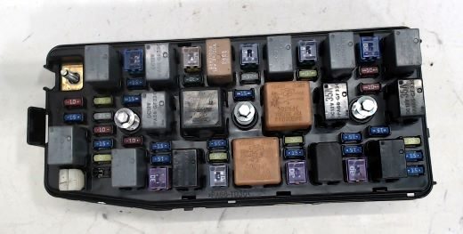
The photo is an example.
| Diagram | ||
|---|---|---|

|
||
| No. | Description of fuses/relays | Amps |
| F1 | Engine control module | 15 |
| F2 | 15 | |
| F3 | 20 | |
| F4 | Engine 3 | 15 / 30 |
| F5 | Air conditioner / heater | 10 |
| F6 | Engine control module | 10 |
| F7 | Starter | 2 |
| F8 | Cooling fan motor | 30 |
| F9 | Antara / Vauxhall fuel pump fuse | 15 |
| F10 | Electronic control unit 4WD | 15 / 20 |
| F11 | Cooling fan motor | 15 / 30 |
| F12 | Stop lamp switch (brake pedal position sensor) | 15 |
| F13 | Spare | 10 / 20 |
| F14 | ABS / ESP system | 20 |
| F15 | 40 | |
| F16 | Horn | 15 |
| F17 | Windshield wiper motor | 25 |
| F18 | Fuse box in the passenger compartment | 40 |
| F19 | Spare | 40 |
| F20 | Sunroof | 20 |
| F21 | Anti-theft system | 15 |
| F22 | Power seat | 30 |
| F23 | Instrument Panel Fuse/Relay Box | 60 |
| F24 | Rear window heater | 30 |
| F25 | Left headlight dipped beam | 15 |
| F26 | Spare | 15 |
| F27 | Spare | 10 |
| F28 | Fog lights | 15 |
| F29 | High beam headlamps | 15 |
| F30 | Rear window wiper motor | 20 |
| F31 | Empty | - |
| F32 | Headlight washers | 20 |
| F33 | Electronic transmission control unit (TOM) | 15 |
| F34 | Spare | 10 |
| F35 | Spare | 25 |
| F36 | 20 | |
| F37 | 15 | |
| F38 | 10 | |
| 1 | Empty | |
| 2 | Fuel pump relay | |
| 3 | Empty | |
| 4 | Rear window heater relay | |
| 5 | Dipped beam relay | |
| 6 | Headlight washer pump relay | |
| 7 | Engine control relay | |
| 8 | Empty | |
| 9 | Empty | |
| 10 | Empty | |
| 11 | Parking lamp relay | |
| 12 | Starter relay | |
| 13 | Air conditioner compressor solenoid clutch relay | |
| 14 | Horn relay | |
| 15 | Empty | |
| 16 | Fog light relay | |
| 17 | Headlamp high beam relay | |
Type 2
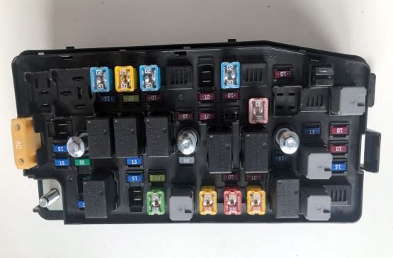
General view.
| Diagram | |
|---|---|

|
|
| Designation | Purpose |
| FUEL/VAC | Fuel pump fuse, vacuum pump |
| HDLP WASHER | headlight washer |
| HI BEAM LH | High beam (left headlamp) |
| HI BEAM RH | High beam (right headlamp) |
| HORN | Beep |
| HTD WASH/MIR | Heated washer fluid, heated exterior mirrors |
| IGN COIL A | Ignition coil |
| IGN COIL B | |
| LO BEAM LH | Dipped beam (left headlamp) |
| LO BEAM RH | Dipped beam (right headlamp) |
| PRK LP LH | Parking light (left headlamp) |
| PRK LP RH | Parking light (right headlamp) |
| PWM FAN | PWM fan control signal |
| REAR DEFOG | Rear window heating |
| REAR WPR | Rear wiper |
| SPARE | – |
| STOP LAMP | Brake lights |
| STRTR | Starter |
| TCM | Transmission control unit |
| TRLR PRL LP | Trailer parking lights |
| ABS | Anti-lock braking system |
| A/C | Climate control system, air conditioning |
| BATT1 | Fuse box in the passenger compartment |
| BATT2 | |
| BATT3 | |
| BCM | Electronic body systems control unit |
| ECM | ECM |
| ECM PWR TRN | ECM, engine and transmission |
| ENG SNSR | Engine control system sensors |
| EPB | Electric parking brake |
| FAN1 | Cooling blower |
| FAN3 | |
| FRT FOG | Front fog lights |
| FRT WPR | Front wiper |
Additional distribution box
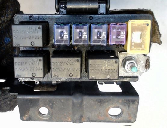
Installed on diesel engine models.
| Diagram | ||
|---|---|---|
|
||
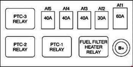
| No. | Purpose | Amps |
| AF1 | Preheating plug controller | 60 |
| AF2 | Fuel filter heater relay | 30 |
| AF3 | Relay PTC-1 | 40 |
| AF4 | 40 | |
| AF5 | 40 | |
In the passenger compartment
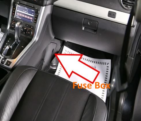
The mounting unit is located on the left side in the passenger footwell. It has several variations.

The photo is an example.
| Diagram | ||
|---|---|---|
| Version No. 1 | ||

|
||
| No. | Purpose | Amps |
| F1 | Power connector for optional equipment | 20 |
| F2 | Front seat heater | 20 |
| F3 | 15 | |
| F4 | Trailer electrical equipment | 10 |
| F5 | 10 | |
| F6 | 10 | |
| F7 | Power steering | 10 |
| F8 | 10 | |
| F9 | 10 | |
| F10 | central locking system | 20 |
| F11 | 15 | |
| F12 | 15 | |
| F13 | 15 | |
| F14 | 15 | |
| F15 | 10 | |
| F16 | 15 | |
| F17 | 20 | |
| F18 | 15 | |
| F19 | 20 | |
| F20 | Rear fog lights | 10 |
| F21 | SRS system | 10 |
| F22 | central locking system | 15 |
| F23 | Power connector for optional equipment | 20 |
| F24 | Electronic transmission control unit (TCM) | 15 |
| F25 | 15 | |
| F26 | 10 | |
| F27 | — | |
| F28 | Windshield washer pump motor | 10 |
| F29 | Rear view mirror heater | 15 |
| F30 | 10 | |
| F31 | 10 | |
| F32 | SRS system | |
| F33 | 20/10 | |
| F34 | 10 | |
| F35 | — | |
| F36 | Opel / Vauxhall Antara cigarette lighter fuse | 20 |
| F37 | Power windows | 20 |
| F38 | 20 | |
| F39 | 10 | |
| 1 | Auxiliary Ignition Relay | |
| 2 | ||
| Version No. 2 | ||

|
||
| No. | Explanation / Amps | |
| F1 | AP01 - Additional power outlet / 20 | |
| F2 | Front seat heater /20 | |
| F3 | Audio system / 15 | |
| F4 | Air conditioner / 10 | |
| F5 | Control unit for body electronic components / 10 | |
| F6 | Door lock / 20 | |
| F7 | Turn signal indicator right side / 15 | |
| F8 | Turn signal indicator left side / 15 | |
| F9 | Stop / 15 | |
| F10 | Headlight washers / 15 | |
| F11 | Air conditioning / 15 | |
| F12 | Control unit for electronic body components / 20-15 | |
| F13 | ||
| F14 | Ignition: S/W/2 | |
| F15 | Rear fog light / 10 | |
| F16 | Airbag (AIR BAG) / 10 | |
| F17 | Front washer / 10 | |
| F18 | Front door lock / 15 | |
| F19 | Additional power outlet / 20 | |
| F20 | Transmission control unit / 15 | |
| F21 | Engine / 15 | |
| F22 | Dipped beam / 10 | |
| F23 | Power windows / 10 | |
| F24 | Exterior mirror heater / 15 | |
| F25 | Instrument panel / 10 | |
| F26 | Ignition 1/10 | |
| F27 | AIR BAG / 10 | |
| F28 | Folding mirror* / 10 | |
| F29 | Cigarette lighter fuse / 20 | |
| F30 | Passenger side power window / 20 | |
| F31 | Driver's side power window / 20 | |
| F32 | Clock / 10 | |
| R1 | Air conditioner relay component / Non-replaceable auxiliary electrical outlet | |
| R2 | Ignition: ON/START | |
| Version No. 3 | ||

|
||
All electronic modules
General layout of the electrical system in the Opel / Vauxhall Antara.

|
|
| No. | Purpose |
| 1 | ABS electronic control unit - under the fuse box in engine compartment 1 |
| 2 | Electronic air conditioner control unit - behind the heater control panel |
| 3 | Auxiliary heater - on the heater fan housing |
| 4 | battery |
| 5 | Diagnostic connector (DLC) |
| 6 | Multifunctional digital display control unit |
| 7 | Electronic Engine Control Module (ECM) |
| 8 | Electronic control unit 4WD - on the rear axle |
| 9 | Fuse and relay box, engine compartment 1 |
| 10 | Additional fuse box, engine compartment 2 - Diesel |
| 11 | Passenger compartment fuse box |
| 12 | Heater Blower Motor Relay - Behind duffel Box |
| 13 | Heater fan motor resistor - behind the duffel box |
| 14 | Glow plug control unit |
| 15 | Horn |
| 16 | |
| 17 | Immobilizer control unit |
| 18 | Instrument cluster control unit |
| 19 | Multifunction control unit 1 - behind the instrument panel-functions:
|
| 20 | Multifunction control unit 2 - behind the instrument cluster - functions:
|
| 21 | Ambient air temperature sensor (automatic temperature control) - behind the bumper |
| 22 | Parking Control Module - Behind Luggage Compartment Trim Panel |
| 23 | Power steering control unit (variable-ratio power steering) - behind the instrument panel |
| 24 | Electric sunroof control unit - behind the roof panel |
| 25 | SRS control unit |
| 26 | Electronic transmission control unit (TCM) |
