Most of the power supply circuits of the Japanese sedan and hatchback are protected by fuses. Headlights, fan motors, fuel pump and other powerful current consumers are connected via relays. Protective elements are installed in distribution boxes that are located under the hood, in the passenger compartment and in the trunk.

Considered fuse circuits of the 8th generation Honda Civic 8 2005, 2006, 2007, 2008, 2009, 2010, 2011, 2012 with a 1.8 l R4 16V 140 hp gasoline engine R18A.
In the passenger compartment
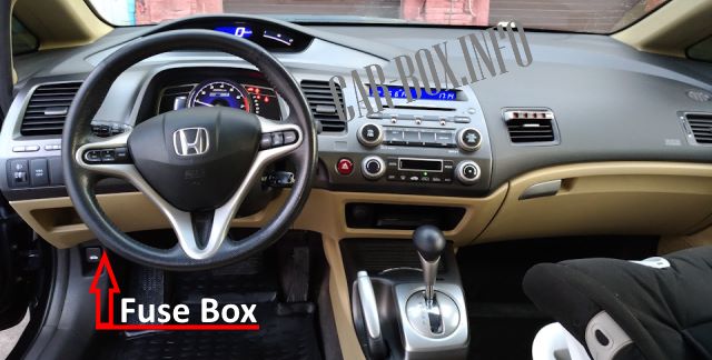
Located on the driver's side under the steering column.
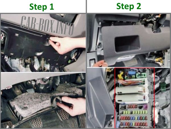
To access it, you need to remove the steering column shield (1). And then the bottom of the dashboard (2).
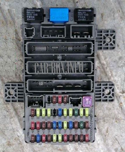
General view.
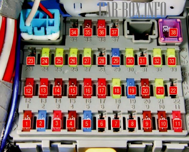
| Assigment of fuses in the Civic 8 passenger compartment | ||
|---|---|---|
|
||
| No. | Description | A |
| 1 | Electric windows | 7.5 |
| 2 | Fuel module (fuel pump fuse) | 15 |
| 3 | IG1 ACG | 10 |
| 4 | Dynamic Stability Assist (VSA) | 7.5 |
| 5 | Seat heating | 15 |
| 6 | Front fog lights | 20 |
| 7 | - | |
| 8 | - | |
| 9 | Front Seat Passenger Detection System (ODS) | 7.5 |
| 10 | Instrument cluster | 7.5 |
| 11 | Supplemental Restraint System (SRS) | 10 |
| 12 | Right headlight (high beam) | 10 |
| 13 | Left headlight (high beam) | 10 |
| 14 | Interior lamps | 7.5 |
| 15 | Outdoor lamps | 7.5 |
| 16 | Right headlight (low beam) | 15 |
| 17 | Left headlight (low beam) | 15 |
| 18 | High beam headlights | 20 |
| 19 | Interior and exterior lighting lamps | 15 |
| 20 | Rear fog lamp | 7.5 |
| 21 | Low beam headlights | 20 |
| 22 | IG1 US | 7.5 |
| 23 | - | |
| 24 | Electric sunroof | 20 |
| 25 | Door locks | 20 |
| 26 | Driver's door window regulator | 20 |
| 27 | Heating and air conditioning system | 20 |
| 28 | Rear socket for connecting additional equipment | 20 |
| 29 | Front socket for connecting additional equipment, cigarette lighter fuse Honda Civic 8 | 20 |
| 30 | Front passenger door window regulator | 20 |
| 31 | headlight washer | 20 |
| 32 | Rear right door window lifter | 20 |
| 33 | Rear left door window lifter | 20 |
| 34 | - | |
| 35 | Audio system | 7.5 |
| 36 | IG2 US | 10 |
| 37 | Daytime Running Lights | 7.5 |
| 38 | Windshield wiper | 30 |
| The purpose of the relay modules in the upper part of the block: | ||

|
||
| R1 | Window lifters | |
| R2 | Fuel pump relay | |
| R3 | Starter | |
In the engine compartment
Fuse box
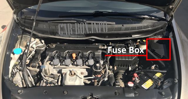
Located near the battery behind a protective cover.

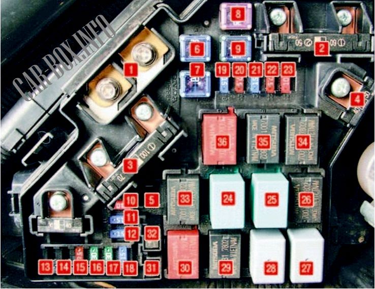
General view of the distribution box.
| Diagram | ||
|---|---|---|
|
||
| No. | Decoding | A |
| 1 | Battery | 100 |
| Electric power steering | 70 | |
| 2 | Ignition system | 50 |
| Main fuse for bodywork | 80 | |
| 3 | ABS system | 40 |
| 20 | ||
| 4 | Headlights | 50 |
| Power windows | 40 | |
| 5 | Not used | |
| 6 | Air conditioner condenser fan | 20 |
| 7 | Cooling system radiator fan | 20 |
| 8 | Heated rear window | 30 |
| 9 | Heater fan | 40 |
| 10 | Emergency | 10 |
| 11 | Supply system | 15 |
| 12 | Horn, brake lights | 15 |
| 13/14 | - | |
| 15 | Engine oil level sensor | 7.5 |
| 16/17 | Not used | |
| 18 | Ignition coils | 15 |
| 19 | Fuel injection main fuse | 15 |
| 20 | A / C compressor clutch fuse | 7.5 |
| 21 | Throttle actuator fuse | 15 |
| 22 | Interior lampshades | 7.5 |
| 23 | Emergency power supply | 10 |
| No. | Relay modules | |
| 24 | heated rear window | |
| 25 | heater motor | |
| 26 | A / C condenser fan relay | |
| 27 | engine cooling fan control | |
| 28 | rear window wiper | |
| 29 | PGM-FI injection override relay | |
| 30 | ignition coils | |
| 31 | Diode of the electric motor of the fan of the engine cooling system | |
| 32 | Air conditioner condenser fan motor diode | |
| 33 | air conditioner clutch | |
| 34 | engine cooling fan | |
| 35 | throttle actuator relay | |
| 36 | PGM-FI MAIN Injection Main Relay | |
Auxilary fuse panel (hybrid only)
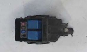
On hybrid models, an add-on unit is located near the battery.
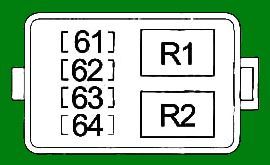
| Diagram | ||
|---|---|---|
|
||
| No. | Description | A |
| 61 | Battery Monitoring Module (BCM), Powertrain Control Module (MCM) Relay # 2, Servo | 10 |
| 62 | Battery Condition Monitoring Module (BCM), Powertrain Control Module (MCM) Relay # 1 | 7.5 |
| 63 | Servo block | 15 |
| 64 | - | - |
| R1 | Additional electric pump of the cooling system | |
| R2 | Fuel pump relay | |

very nice