
The Hyundai ix35 is the successor to the first-generation Tucson. The vehicle debuted at the Frankfurt Motor Show on September 3, 2009. This article provides detailed fuse box diagrams and relay assignments for the second-generation Hyundai ix35 / Tucson (LM chassis) produced from 2009 through 2015.

Here you will find fuse box locations, diagram photos, and detailed circuit descriptions, including the specific fuse designated for the fuel pump.
In the engine compartment
Depending on the engine type (gasoline or diesel), the engine compartment contains either one or two power distribution boxes.
Primary fuse box
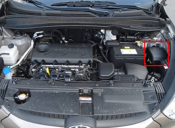
Located on the left side of the engine compartment, directly behind the battery.
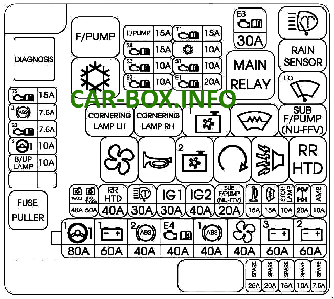
Fuse box cover legend diagram example.
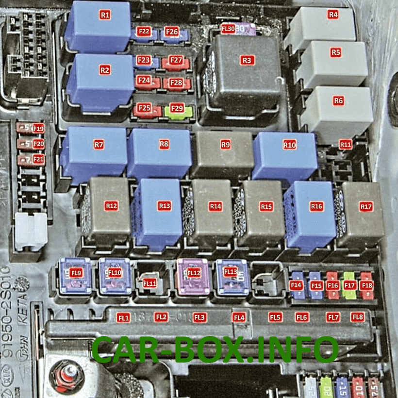
Type 1
First variant of the engine compartment fuse box layout.
| Diagram | ||
|---|---|---|
|
||
| No. | Protected Component / Circuit | Rating (A) |
| FL1 | Motor-Driven Power Steering (MDPS) | 80 |
| FL2 | Instrument panel Smart Junction Box (SJB) | 60 |
| FL3 | ESC / ABS control module | 40 |
| FL4 | Engine Management System (EMS) box | 40 |
| FL5 | ESC / ABS control module | 40 |
| FL6 | Blower motor relay | 40 |
| FL7 | Instrument panel Smart Junction Box (SJB) | 60 |
| FL8 | Instrument panel Smart Junction Box (SJB) | 60 |
| FL9 | Electric cooling fan | 40 |
| FL10 | Heated rear glass / Defogger | 40 |
| FL11 | Headlamp washer | 30 |
| FL12 | Ignition switch | 40 |
| FL.13 | Starter relay, ignition switch | 40 |
| F14 | Alarm siren relay | 15 |
| F15 | Windshield wiper de-icer | 15 |
| F16 | Brake light switch | 10 |
| F17 | All-Wheel Drive (AWD) control module | 20 |
| F18 | Ignition coils, condenser | 20 |
| F19 | Starter relay, A/T park/neutral position switch, MAF sensor, multifunction switch | 7.5 |
| F20 | ESC, ABS, and ICM control modules, multifunction switch, glow plug relay unit, fuel filter water sensor, fuel filter heater relay | 7.5 |
| F21 | Automatic transmission gear selector switch | 7.5 |
| F22 | Fuel pump fuse | 15 |
| F23 |
|
15 |
| F24 |
|
10 |
| F25 | Brake light switch | 10 |
| F26 |
|
15 |
| F27 | Air conditioning compressor | 10 |
| F28 |
|
10 |
| F29 | Ignition coils, Engine Control Module (ECM) | 20 |
| FL30 | Main engine control relay | 30 |
| R1 | Fuel pump relay | |
| R2 | A/C compressor relay | |
| R3 | Main engine control relay | |
| R4 | Brake warning relay / Headlamp washer relay | |
| R5 | Windshield wiper relay (rain sensor) | |
| R6 | Windshield wiper relay (low speed) | |
| R7 | Blower motor relay | |
| R8 | Horn relay | |
| R9 | Cooling fan high-speed relay | |
| R10 | Windshield de-icer relay | |
| R11 | Engine control relay | |
| R12 | HVAC blower motor relay | |
| R13 | Horn relay | |
| R14 | Cooling fan low-speed relay | |
| R15 | Starter relay | |
| R16 | Burglar alarm siren relay | |
| R17 | Rear window defogger relay | |
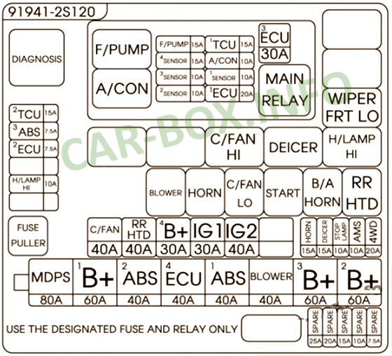
Type 2
Second variant of the engine compartment fuse box layout.
| Diagram | ||
|---|---|---|
|
||
| Name | Description | Rating (A) |
| MDPS | Motor-Driven Power Steering (MDPS) control module | 80 |
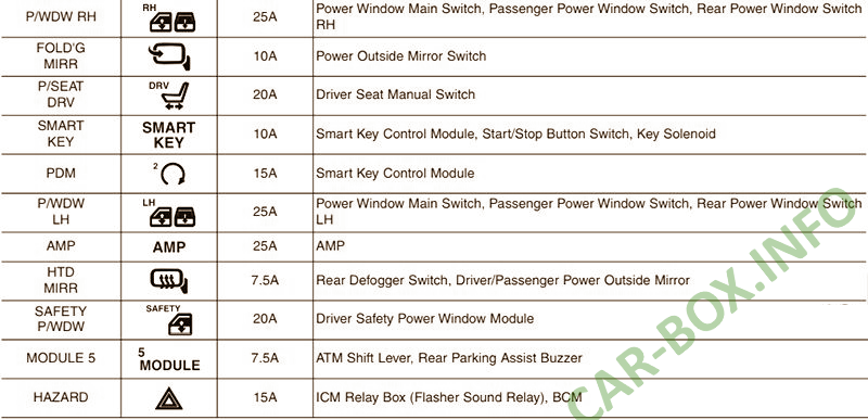
| B+1 | Smart Junction Box (DR LOCK 15 A, HAZARD 15 A, PDM 15 A, RR S/HEATER 15 A) | 60 |
| ABS 2 | Data Link Connector (DLC) / Multipurpose check connector, ESC module | 40 |
| ECU 4 | EMS Box (TCU 1 15 A, ECU 3 30 A, A/C 10 A, F/PUMP 15 A) | 40 |
| ABS 1 | Data Link Connector (DLC) / Multipurpose check connector, ESC module | 40 |
| BLOWER | Blower motor relay | 40 |
| B+3 | Smart Junction Box (DRV P/SEAT 20 A, SAFETY POWER WINDOW 20 A, SMART KEY 10 A, MODULE 5 7.5 A, Power Connector [AUDIO 1 10 A, ROOM LAMP 10 A], IPS-1CH, IPS-2CH) | 60 |
| B+2 | Smart Junction Box (Power Window Relay, SUNROOF 15 A, AMP 25 A, IPS-1CH) | 60 |
| C/FAN | Engine Compartment Fuse & Relay Box (C/FAN LO Relay, C/FAN HI Relay) | 40 |
| RR HTD | Engine Compartment Fuse & Relay Box (Rear Defogger Relay) | 40 |
| B+ 4 | Engine Compartment Fuse & Relay Box (H/LAMP HI 10 A) | 30 |
| IG 1 | Ignition Switch, PDM Relay Box (IGN 1 Relay) | 30 |
| IG 2 | Engine Compartment Fuse & Relay Box (Start Relay), Ignition Switch, PDM Relay Box (IGN 2 Relay) | 40 |
| HORN | Engine Compartment Fuse & Relay Box (Horn Relay, Alarm Horn Relay) | 15 |
| DEICER | Engine Compartment Fuse & Relay Box (De-icer Relay) | 15 |
| STOP LAMP | Stop lamp switch, Stop signal electronic module, Smart Key control module | 10 |
| AMS | Battery monitoring sensor (AMS) | 10 |
| 4WD | AWD / 4WD ECM | 20 |
| H/LAMP HI | Engine Compartment Fuse & Relay Box (High-Beam Headlamp Relay) | 10 |
| ECU 2 | PCM / ECM, clock spring | 7.5 |
| ABS 3 | Data Link Connector (DLC) / Multipurpose check connector, ESC module | 7.5 |
| TCU 2 | Transmission range switch (A/T), vehicle speed sensor (M/T), reverse light switch (M/T) | 15 |
| F/PUMP | EMS Box (F/PUMP Relay) | 15 |
| SENSOR 4 | Engine Compartment Fuse & Relay Box (C/FAN HI/LO Relays), EMS Box (F/PUMP Relay), Oxygen sensors (Upstream, Downstream) | 15 |
| SENSOR 3 | EMS Box (A/C Relay) | 10 |
| SENSOR 2 | (Not Used) | 10 |
| SENSOR 1 | PCM | 10 |
| TCU 1 | EMS Box (A/C Relay) | 15 |
| A/CON | Immobilizer module, crankshaft position sensor, camshaft position sensors 1/2, oil control valves 1/2, EVAP purge control solenoid valve, variable intake manifold valve, canister close valve | 10 |
| ECU 1 | Ignition coils (#1, #2, #3, #4), condenser | 20 |
| ECU 3 | EMS Box (Engine Control Relay) | 30 |
Auxiliary fuse box
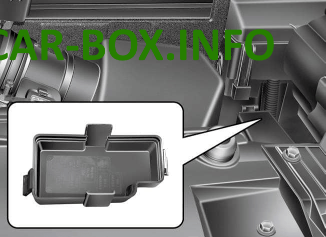
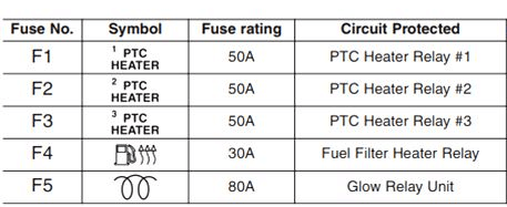
Installed exclusively on models equipped with a diesel engine.

Main fuse
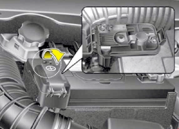
On Hyundai ix35 vehicles, the main power fuse (fusible link) is mounted directly on the positive battery terminal.
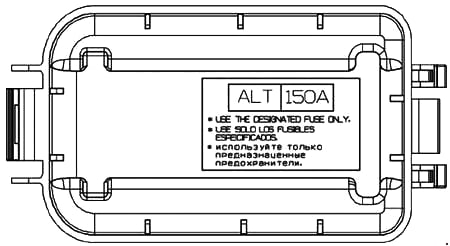
ALT – Alternator (150 A).
In the passenger compartment
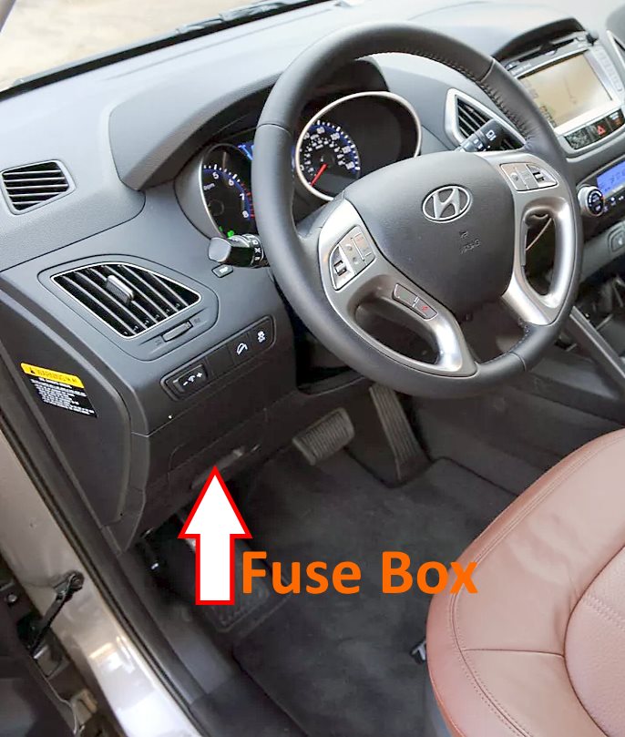
Located behind the lower driver-side dashboard panel. Pull the panel cover toward you in the direction of the arrow to gain access.

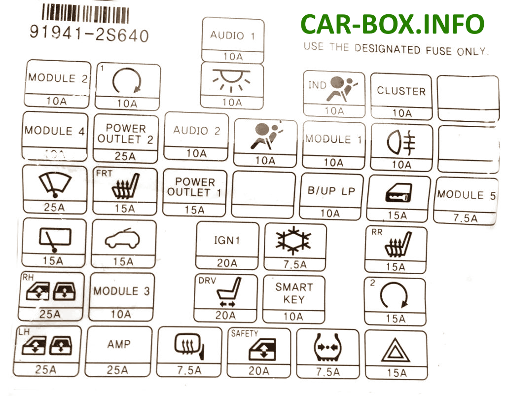
Overview of the Hyundai ix35 / Tucson interior passenger compartment fuse box.
| Diagram | ||
|---|---|---|
|
||
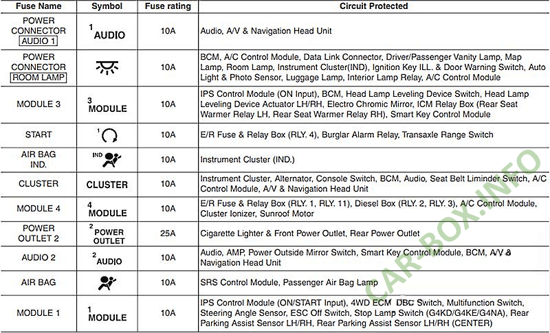
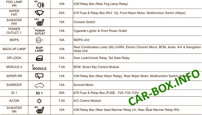
| Description | ||
|
||
|
||
|
