The Hyundai Creta (also known as ix25 and Cantus) is a mini crossover vehicle launched by the Korean car company in June 2014. In this article, we will take a detailed look at the fuse box diagrams for the Hyundai Creta (first generation; GS index) 2015, 2016, 2017, 2017, 2018, 2019, 2020, 2021 years of manufacture.

Here you will find the locations and photos of distribution boxes. The fuses responsible for the “Cigarette lighter” and “Fuel Pump” are highlighted in bold.
In the engine compartment
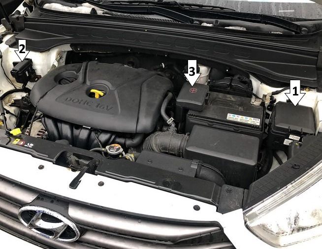
General arrangement
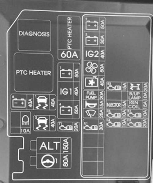
Main fuse box

It is located on the left side of the engine compartment.

Access example.
| Diagram | |
|---|---|
|
|
| Name | Amps / Description |
| MDPS | Motor Driven Power Steering Unit 80A |
| ALT |
|
| ECU2 | G4FC engine: ECU (M / T), PCU (A / T) 10A D4FC engine: CAM SNSR, Glow RLY, WGT, EGR Control Valve, SNSR Airflow, IMMO 15A D4FB engine: CAM SNSR, VGT Vacuum, IMMO 15A |
| HEAD LAMP HIGH BEAM | High Beam Solenoid Relay (Dual Function) |
| ABS2 | ABS / ESC control unit |
| ECU 4 |
|
| TCU 1 | D4FB: TCU (automatic transmission) |
| BAT + 5 | Instrument panel fuse box fuse: FS01 |
| ABS 1 | ABS / ESC control unit, engine compartment diagnosis |
| BAT + 4 | Instrument panel fuse box fuse: FS06, IPS-1, IPS-2, IPS-3 |
| IG1 | Without start button: SW ignition With button start: PDM relay box |
| BAT + 1 | Instrument panel fuse box fuse: FS14, FS05, FS13, FS17, FS10, FS02, FS09, IOD relay (auto leakage current cutoff) |
| GLOW | D4FC / D4FB: glow plug relay, glow plug |
| FUEL HEATER | D4FC / D4FB: Fuel heater |
| ECU 1 | (Engine control) Main relay |
| FRONT WIPER | Wiper motor (front) |
| HORN | Buzzer (double), burglar alarm buzzer |
| FUEL PUMP | G4FC: fuel pump relay, fuel pump motor |
| C / FAN |
|
| BLOWER | Fan motor |
| IG2 | Without start button: start relay, start solenoid, SW ignition With button start: start relay, start solenoid, PDM relay box |
| BAT + 3 | Instrument panel fuse box fuse: FS04, IPS-4, IPS-5 |
| BAT + 2 | Dashboard fuse box fuse: FS03, P / window relay, P / output relay |
| INJECTOR | G4FC engine: Injector (# 1, # 2, # 3, # 4) |
| BACK UP LAMP | Reverse switch (MT only), rear combination lamp, left / right |
| IGN COIL | G4FC engine: capacitor, ignition coil, int. |
| SENSOR 1 | G4FC engine: variable intake solenoid, variable outlet cam (IN, EX), purge control solenoid valve, oxygen sensor (UP, DN), IMMO D4FB: lambda probe, stop switch, exhaust gas recirculation actuator, D4FC: stop switch |
| ECU 3 | D4FC / D4FB engines: ECU G4FC: ECU (M / T), PCU (A / T) |
| GLOW | D4FC / D4FB engines: Glow plug |
Some additional relays can be attached to the back of the unit.
Additional distribution box
Depending on the level of equipment, some models have an additional unit installed.
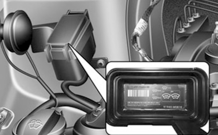
Refer to the current diagram on the back of the cover. The fuses and relays responsible for the auxiliary heater and window defroster are located there.
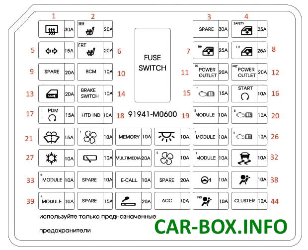
In the passenger compartment

Located under the dashboard on the driver's side behind the protective cover.

General view.
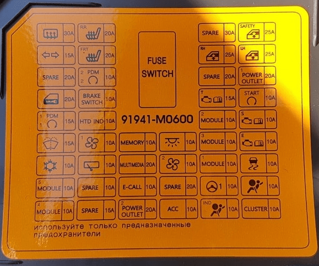
Example of a diagram from the block cover.
| Diagram | ||
|---|---|---|
|
||
| № | Description | Amps |
| 1 | rear window defogger relay | 30 |
| 2 | rear seat heater control module | 20 |
| 3 | reserve | 30 |
| 4 | anti-jamming driver electric glass module | 25 |
| 5 | direction indicator and alarm | 15 |
| 6 | driver / passenger seat heater control module | 20 |
| 7 | right power window | 25 |
| 8 | left power window | 25 |
| 9 | reserve | 20 |
| 10 | electronic key ECU, immobilizer module | 10 |
| 11 | rear power outlet | 20 |
| 12 | front power outlet (cigarette lighter) | 20 |
| 13 | lock / unlock relay, tailgate unlock relay | 20 |
| 14 | ecu electronic keys, brake light switch | 10 |
| 15 | manual transmission range switch PP unit (fuse - f26 (reversing lights)) | 15 |
| 16 | control unit (alarm relay), transmission range selector switch, ECU, electronic key and start ECU, ignition switch and clutch pedal position sensor | 10 |
| 17 | ecu electronic keys | 15 |
| 18 | heated mirrors | 10 |
| 19 | Console switch, 4wd ecm, reverse parking assist buzzer, left/right reverse parking assist sensors, left/right center reverse parking assist sensors | 10 |
| 20 | reserve | 10 |
| 21 | multifunction switch, washer | 15 |
| 22 | air conditioning control module | 10 |
| 23 | door mirror adjuster, digital clock, air conditioning control module, instrument cluster, data line connector | 10 |
| 24 | interior lamps, luggage compartment light, directional light, passenger compartment light, front left/right auxiliary lamps | 10 |
| 25 | Body control module, selector lever position indicator, air conditioning control module, AV head unit with navigation, electronic call module, driver/passenger seat heating control module, rear seat heating control module | 10 |
| 26 | pcm / ecm, electronic key ECU, immobilizer module | 10 |
| 27 | engine compartment junction box (relay 1 - heater relay ptk) PP unit (horn relay), air conditioning control unit | 10 |
| 28 | PP block (rear wiper relay), rear wiper motor | 10 |
| 29 | audio system, audio-visual head unit with navigation | 20 |
| 30 | air conditioning control unit, horn switch, horn resistor | 10 |
| 31 | body control module, brake light switch | 10 |
| 32 | front panel switch, esp control unit | 10 |
| 33 | Electrochromic mirror, rear seat heater control module, headlight leveling switch, left/right headlight washer nozzle heater, driver/passenger seat heater control module, auxiliary junction box (relay 2/3 - left/right front wiper) | 10 |
| 34 | reserve | 10 |
| 35 | mts e-call module | 10 |
| 36 | reserve | 20 |
| 37 | with mdps - mdps unit, without mdps - steering wheel angle sensor | 10 |
| 38 | srs control module - airbags | 10 |
| 39 | body control module, electronic keys | 10 |
| 40 | heated steering wheel | 15 |
| 41 | Hyundai Creta cigarette lighter fuse | 20 |
| 42 | rear outlet relay, bcm, digital clock, e-call module, audio system, audiovisual head unit with navigation, smartphone holder, electronic key ecu, rearview mirror adjuster | 10 |
| 43 | instrument cluster, airbag indicator | 10 |
| 44 | instrument cluster | 10 |
Individual non-removable relays (PCB MINI) can be located on the rear panel of the device.
