The second generation Santa Fe made its debut at the 2006 North American International Auto Show. The first production vehicle rolled off the Hyundai assembly line in Montgomery, Alabama on 18 April 2006. In this article, we will take a detailed look at the fuse box diagrams for the Hyundai Santa Fe (second generation; CM index) 2006, 2007, 2008, 2008, 2009, 2010, 2011, and 2012 years of manufacture.

Here you will find the locations and photos of distribution boxes. The fuses responsible for the “Cigarette lighter” and “Fuel Pump” are highlighted in bold.
In the engine compartment

There are two fuse boxes in the engine compartment: main (1) and auxiliary (2).
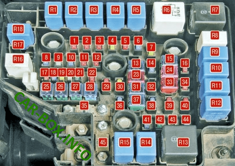
Main fuse box

Located on the left side of the engine compartment.
| Diagram | ||
|---|---|---|
|
||
| № | Description | A |
| 1 | B / UP LP - Speed sensor, automatic transmission control unit | 10 |
| 2 | H / LP - headlight unit | 10 |
| 3 | ECU - Engine control unit, automatic transmission control unit | 10 |
| 4 | H / LP HI - High beam lamps | 20 |
| 5 | SENSOR - Immobilizer, fuel pump relay, heating, air conditioning and ventilation system relay | 10 |
| 6 | SENSOR - mass air flow sensor, oxygen concentration sensors | 15 |
| 7 | IG COIL - Ignition coils | 20 |
| 8 | Santa Fe fuel pump fuse | 15 |
| 9 | FR WIPER - Windscreen washer, rain sensor, windscreen wiper | 25 |
| 10 | TCU - Automatic transmission control unit | 15 |
| 11 | ABS - Anti lock brake system (ABS) control unit | 10 |
| 12 | COOLING - Heating, air conditioning and ventilation system | 10 |
| 13 | IGN - Ignition switch (lock) | 40 |
| 14 | SENSOR - Engine control unit, solenoid valves for timing change | 15 |
| 15 | ECU MAIN - Engine control unit | 40 |
| 16 | TAIL LH - Left rear sidelight bulb | 10 |
| 17 | SPARE | - |
| 18 | SPARE | - |
| 19 | SPARE | - |
| 20 | SPARE | - |
| 21 | SPARE | - |
| 22 | FR FOG - Fog lamps | 10 |
| 23 | B + - Main fuse | 50 |
| 24 | CON FAN - Heating, air conditioning and ventilation system | 30 |
| 25 | IGN - Ignition switch (lock), starter relay | 40 |
| 26 | ABS - Anti lock brake system (ABS) control unit | 40 |
| 27 | RAD FAN - Engine cooling radiator fan motor | 40 |
| 28 | ABS - Anti lock brake system (ABS) control unit | 20 |
| 29 | A / CON - Heating, air conditioning and ventilation system | 10 |
| 30 | ATM - Body ECM, ECM, Automatic Transmission Control Module, Reversing Lights | 20 |
| 31 | P / WDW - Power windows | 40 |
| 32 | Reserve | - |
| 33 | B + - Anti-theft alarm system, power seat control unit, fog lights, headlight washer | 50 |
| 34 | TAIL RH - Right rear sidelight bulb | 10 |
| 35 | DSL - Fuse block | 125 |
| 36 | HORN - Sound signal | 15 |
| 37 | BLR - Engine cooling system radiator fan motor | 40 |
| 38 | H / LP LO LH - Dipped beam bulb of the left headlamp | 15 |
| 39 | H / LP HI IND - Instrument cluster | 10 |
| 40 | ALT DSL - Alternator | 10 |
| 41 | DEICER - Windscreen blowing mode | 15 |
| 42 | RR HTD - Heated tailgate window | 30 |
| 43 | Reserve | - |
| 44 | H / LP LO RH - Low beam lamp, right headlamp | 15 |
| 45 | ALT - Main fuse | 150 |
| Relay modules | ||
| R1 | ATM - Reverse lights | |
| R2 | RAD FAN - Radiator Fan Motor | |
| R3 | FR FOG - Fog lamps | |
| R4 | A / CON - heating, air conditioning and ventilation | |
| R5 | A / CON - High beam lamps | |
| R6 | ECU MAIN - Engine control unit | |
| R7 | START - Starter | |
| R8 | CON FAN - heating, air conditioning and ventilation | |
| R9 | CON FAN - heating, air conditioning and ventilation | |
| R10 | TAIL LP - Side light bulbs | |
| R11 | H / LP LO LH - dipped beam left headlamp | |
| R12 | H / LP LO RH - dipped beam right headlamp | |
| R13 | RR HTD - rear door window electric heating | |
| R14 | DEICER - blowing windshield | |
| R15 | HORN | |
| R16 | FR WIPER - windshield washer | |
| R17 | RAIN SNRS - Rain sensor | |
| R18 | Hyundai Santa Fe Fuel pump relay | |
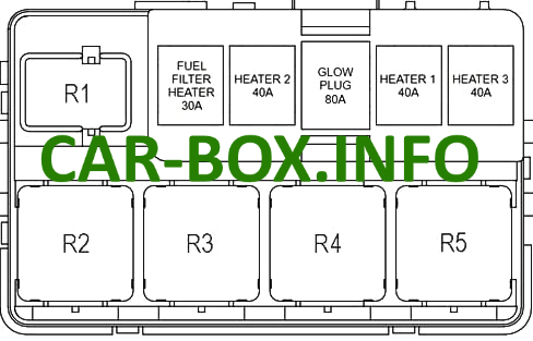
Additional fuse block

It is installed mainly on models with diesel engines.
| Diagram | ||
|---|---|---|
|
||
| № | Amps / Description | A |
| GLOW | Glow plug relay | 80 |
| FUEL | Fuel filter heater relay | 30 |
| PTC # 1 | Heater relay PTC 1 | 40 |
| PTC # 2 | ||
| PTC # 3 | ||
| R1 | Fuel filter heater | |
| R2 | Heater PTC 2 | |
| R3 | Reserve | |
| R4 | Heater PTC 1 | |
| R5 | Heater PTC 3 | |
In the passenger compartment

Located under the dashboard behind the protective cover.
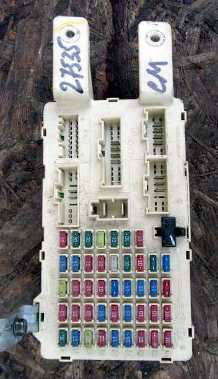
General view of the Hyundai Santa Fe interior fuse box.
| Diagram | ||
|---|---|---|
|
||
| № | Description | A |
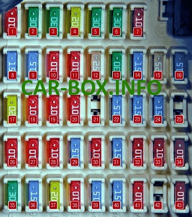
| 1 | START - Anti-theft system | 10 |
| 2 | P / WDW LH - Power window, left rear door | 30 |
| 3 | P / WDW RH - Power window, right rear door | 30 |
| 4 | S / ROOF - sunroof | 20 |
| 5 | P / SEAT - Power seat control unit | 30 |
| 6 | SAFATY PWR - Module power windows | 30 |
| 7 | MIRR HTD - Mirror control unit | 10 |
| 8 | A / BAG 2 - Passive safety system control unit, Airbags | 15 |
| 9 | A / BAG 1 - Passive safety system control unit, Airbags | 15 |
| 10 | ROOM LP - Instrument panel, lamps for front door light bulbs, lamps for interior lights | 10 |
| 11 | A / CON - Heating, air conditioning and ventilation control unit | 10 |
| 12 | S / WARMER - Driver and front passenger seat heating switches | 25 |
| 13 | P / AMP - Audio amplifier | 30 |
| 14 | P / OUTLER CTR - 12 V socket for connection of auxiliary equipment in the floor tunnel liner | 15 |
| 15 | P / OUTLET - 12V Socket for connecting additional equipment in the luggage compartment | 25 |
| 16 | C / LIGHTER - Cigarette lighter fuse | 15 |
| 17 | DR / LOCK - Central locking system of door locks | 20 |
| 18 | A / BAG IND - Instrument cluster | 10 |
| 19 | ATM LOCK - Exterior light switch lever, steering shaft position sensor, ESP switch | 10 |
| 20 | T / SIG - Hazard switch | 10 |
| 21 | Reserve | - |
| 22 | ADG PEDAL - Brake light switch | 15 |
| 23 | HAZARD - Hazard switch, exterior light switch lever, body electrical control unit, mirror control unit | 15 |
| 24 | RR WIPER - Rear door wiper | 15 |
| 25 | Reserve | - |
| 26 | A / CON SW - Heating, air conditioning and ventilation control unit | 10 |
| 27 | CLASTER - Instrument panel, audio head unit, tire pressure monitoring module (depending on equipment) | 10 |
| 28 | BCM 1 - Body control module | 10 |
| 29 | FUEL LID - Fuel filler cap lock actuator | 15 |
| 30 | B / ALARM HORN - Sound alarm of the anti-theft system | 10 |
| 31 | RR A / CON - Heating, air conditioning and ventilation control unit | 15 |
| 32 | RR FOG / BWS - Fog lamps | 10 |
| 33 | IMS - Rain sensor | 10 |
| 34 | AUDIO 2 - Audio system head unit, digital clock, mirror control unit | 10 |
| 35 | BLOWER - Air blower | 30 |
| 36 | STOP LP - Brake light switch | 15 |
| 37 | DRL - Daytime running lights | 20 |
| 38 | BCM 3 - Body electronic control module | 10 |
| 39 | CLOCK - Digital clock | 15 |
| 40 | AUDIO 1 - Audio system head unit, digital clock | 15 |
| 41 | ATM - Interior lamps, luggage compartment lamp, instrument cluster | 10 |
| 42 | Reserve | - |
| 43 | BCM 2 - Power seat control unit | 10 |
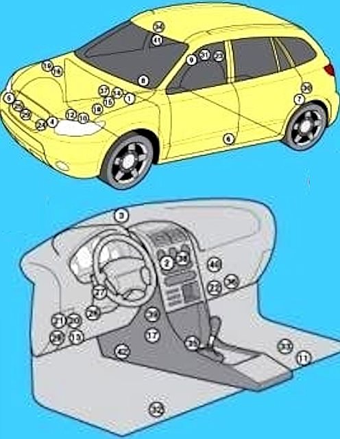
General arrangement
Location of the electronic control units.
|
|
| 1 | ABS electronic control unit - near the brake booster |
| 2 | Air conditioning / heater control unit - in the air conditioning / heater control panel |
| 3 | Sunlight sensor (air conditioning system) |
| 4 | Shock sensor (SRS), left. |
| 5 | Shock sensor (SRS), right |
| 6 | Side impact sensor, driver's side - B-pillar |
| 7 | Side impact sensor, rear left |
| 8 | Side impact sensor, passenger side - B-pillar |
| 9 | Side impact sensor, rear right |
| 10 | Anti-theft alarm horn - Left suspension strut |
| 11 | Audio Output Amplifier - Under Seat |
| 12 | Accumulator battery |
| 13 | Diagnostic connector (DLC) 1 (16-pin) |
| 14 | Diagnostic connector (DLC) 2 (20-pin) - near the brake booster |
| 15 | Electronic engine control unit |
| 16 | Electronic control unit for engine mounts |
| 17 | Engine oil level control unit - behind the center of the dashboard |
| 18 | Fuse and relay box, engine compartment 1 |
| 19 | Fuse and relay box, engine compartment 2 |
| 20 | Fuse / relay box, instrument panel |
| 21 | Heater blower motor relay - in the under-dash fuse / relay box |
| 22 | Heater blower motor resistor (front) - behind the glove box |
| 23 | Heater blower motor resistor (with rear air conditioner) - right side of luggage compartment |
| 24 | Horn, lion. |
| 25 | Sound signal, right. |
| 26 | Electronic immobilizer control unit - on the steering column |
| 27 | Immobilizer ring antenna - near the ignition switch |
| 28 | Multifunction control unit - in the underhood fuse / relay box - functions: Air conditioning / heater fan motor, anti-theft system, central locking, daytime running lights, heated door mirrors, fully closed doors, power windows, fog lights, warning lights, headlight washers, rear window defogger, interior lamps, front position lights, rear position lights, windshield wiper / washer |
| 29 | Ambient temperature sensor |
| 30 | Parking system control unit - luggage compartment left |
| 31 | Rear window wiper / washer control unit - C-pillar |
| 32 | Driver's seat heating control unit - under the seat |
| 33 | Passenger Seat Heating Control Unit - Under Seat |
| 34 | Sunroof motor control unit - in the sunroof motor |
| 35 | SRS electronic control unit |
| 36 | Transfer case control unit - next to the heater blower motor |
| 37 | Electronic gearbox control unit (automatic transmission) - petrol - in the electronic engine control unit |
| 38 | Electronic gearbox control unit (automatic transmission) - Diesel - behind the glove box |
| 39 | Selector lever and / or ignition key lock control unit |
| 40 | Transmission control relay 1 |
| 41 | Rain sensor (windscreen wiper) ∕ Sun sensor |
| 42 | Side Displacement Sensor - Under Mat |
