The Ceed, until 2018 used cee'd, is a C-segment (European classification) car developed by Kia Motors and produced since 2006. It was first introduced on September 28, 2006 at the Paris Motor Show. In the hierarchy, the car occupied the gap between Rio and Magentis. In this article, we will take a detailed look at the fuse box diagrams for the Kia Ceed (second generation; JD index) 2012, 2013, 2014, 2015, 2016, 2017 and 2018 years of manufacture.

Here you will find the locations and photos of distribution boxes. The fuses responsible for the “Cigarette lighter” and “Fuel Pump” are highlighted in bold.
In the engine compartment
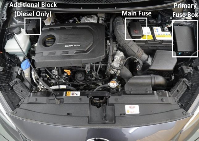
Location of components.
Main fuse
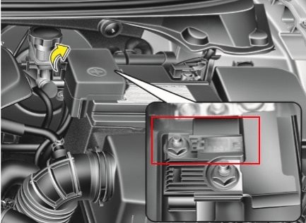
It is located on the battery's plus terminal.
Primary fuse box
It is located behind the protective cover on the left side.

General view.
| Diagram | ||
|---|---|---|

|
||
| № | Legend | A |
| 1 | Spare | 25 |
| 2 | Spare | 7.5 |
| 3 | Reversing light - B / UP LP | 10 |
| 4 | Electronic engine control unit, immobilizer, keyless entry system - ECU4 | 15 |
| 5 | Anti lock brakes ABS, ESC - ABS3 | 10 |
| 6 | Electronic control unit for automatic transmission, brake lights - TCU2 | 15 |
| 7 | Spare | 10 |
| 8 | Spare | 15 |
| 9 | Spare | 20 |
| 10 | Fuel Pump Fuse - F / PUMP | 15 |
| 11 | Electronic engine control unit - ECU3 | 15 |
| 12 | Sound signals - HORN | 15 |
| 13 | Fuel pump - INJECTOR | 10 |
| 14 | engine control unit - ECU2 | 10 |
| 15 | Ignition Coils - IGN COIL | 20 |
| 16 | Starter, variable valve timing system - ECU9 | 10 |
| 17 | engine control unit - ECU1 | 20 |
| 18 | Oxygen sensors, intake pipe duct length change system, canister purge valve - ECU8 | 10 |
| 19 | Heated windshield - DEICER | 15 |
| 20 | Brake lights, hill start assist - STOP LAMP | 15 |
| 21 | engine control unit - TCU1 | 20 |
| 22 | control unit for automatic gearbox - DCT1 | 40 |
| 23 | Fuses # 10-18 - EMS | 40 |
| 24 | Passenger compartment fuse box - B + 3 | 50 |
| 25 | Electro heater fan - BLOWER | 50 |
| 26 | Air Conditioning - A / CON | 10 |
| 27 | Rain sensor - WIPER FRT | 10 |
| 28 | Heated rear window - RRHTD | 40 |
| 29 | Ignition Switch, passenger compartment fuse box - IG1 | 40 |
| 30 | Electronic control unit for automatic transmission - DCT2 | 40 |
| 31 | Electric parking brake - EPB1 | 30 |
| 32 | Electric parking brake - EPB1 | 30 |
| 33 | Electro Radiator Fan - C / FAN | 40 |
| Relay assignment | ||
| R1 | Radiator fan relay (low speed) | |
| R2 | Radiator fan relay (high speed) | |
| R3 | Emergency Brake Warning Relay - ESS | |
| R4 | Heater fan relay - BLOWER | |
| R5 | Heated rear window relay - RR HTD | |
| R6 | Ignition system relay - IG2 | |
| R7 | Wiper relay - WIPER | |
| R8 | Ignition system relay - IG1 | |
| R9 | Starter relay - START | |
| R10 | Ignition Switch Relay - ACC | |
| R11 | Additional heater relay - PTC | |
| R12 | Hill Start Assist Relay - H / LP LO | |
Power fuse panel
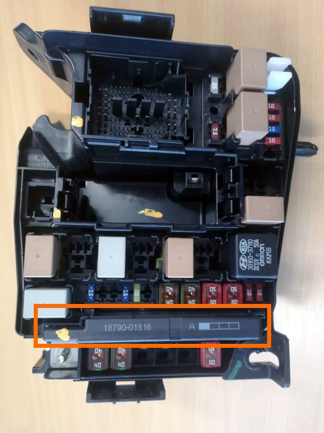
Located inside the main unit.
| Diagram | ||
|---|---|---|

|
||
| № | Legend | A |
| 1 | Electro power steering | 80 |
| 2 | Fuse block in the passenger compartment, left block headlight, turn signal lamps, daytime running lights | 60 |
| 3 | Anti lock brakes ABS, ESC | 40 |
| 4 | Anti lock brakes ABS, ESC, diagnostic connector | 40 |
| 5 | Ignition switch, starter | 40 |
| 6 | Not used | 40 |
| 7 | Additional heater | 60 |
| 8 | fuse block in the passenger compartment, right headlight block, fog lights, taillights | 50 |
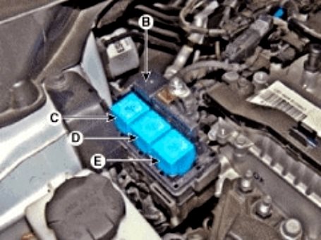
Additional distribution box

It is installed on vehicles with a diesel engine.
| Diagram |
|---|
|
| Description |
| A: PTC (petrol) / fuel heater relay (diesel) |
| B: Glow plug relay |
| C: PTC relay |
| D: PTC relay |
| E: PTC relay |
In the passenger compartment
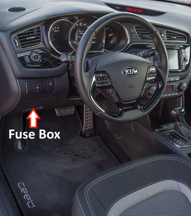
Located behind the protective cover at the bottom of the dashboard.
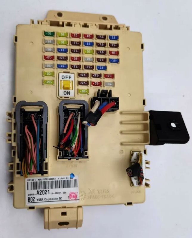
General view of the Kia Ceed interior fuse box.
| Diagram | ||
|---|---|---|

|
||
| № | Description | Amps |
| 1 | Power Driver Seat - P / SEAT DRV | 30 |
| 2 | Headlight washer - H / LP WASHER | 25 |
| 3 | Power windows (right side) - P / WDW RH | 25 |
| 4 | Electric tailgate lock - T / GATE OPEN | 10 |
| 5 | Power windows (left side) - P / WDW LH | 25 |
| 6 | Central locking - DR LOCK | 20 |
| 7 | Spare | 20 |
| 8 | Kia Ceed cigarette lighter fuse, rear power outlet - POWER OUTLET 2 | 20 |
| 9 | Power driver seat - P / SEAT ASS | 20 |
| 10 | Tailgate window wiper - RR WIPER | 15 |
| 11 | Automatic headlight switching system, automatic transmission selector lock, emergency stop switch - MODULE 3 | 7.5 |
| 12 | Heated front seats - S / HEATER FRT | 15 |
| 13 | Audio system, clock, keyless entry system, body electrical control module (BCM), power outside mirrors - ACC | 10 |
| 14 | Air conditioner - A / CON | 7.5 |
| 15 | Headlight washer, rain sensor, body electrical control module (BCM), automatic dimming door mirrors, power sunroof, keyless entry, heated front seats - IG2 | 7.5 |
| 16 | Heated exterior mirrors, air conditioning - HTD MIRR | 10 |
| 17 | Interior lighting - INTERIOR LAMP | 7.5 |
| 18 | Keyless entry system, engine start and stop button - PDM2 | 7.5 |
| 19 | Anti-theft alarm - B / HORN | 7.5 |
| 20 | sunroof | 20 |
| 21 | Electric parking brake, electric headlight range control, air conditioning, parking assist, headlights, automatic transmission selector lever position indicator, illuminated instrument panel switches, heated front seats - MODULE 2 | 10 |
| 22 | Steering wheel heating - HTD STRG | 15 |
| 23 | Engine compartment fuse and relay box - IG1 | 20 |
| 24 | Windshield wiper, rain sensor - WIPER | 25 |
| 25 | Immobilizer - MEMORY 2 | 7.5 |
| 26 | Power outside mirrors, central locking, instrument cluster, air conditioning, tire pressure monitoring system, parking assist, ignition switch illumination, body control module (BCM) - MEMORY 1 | 7.5 |
| 27 | Keyless Entry System, brake lights BRAKE SWITCH | 10 |
| 28 | Instrument cluster, clock - CLUSTER | 7.5 |
| 29 | Electric power steering - POWER STEERING | 7.5 |
| 30 | SPARE | 7.5 |
| 31 | Starter, ignition switch, automatic transmission selector position sensor, automatic transmission control unit - START | 7.5 |
| 32 | Audio system, clock - MULTIMEDIA | 15 |
| 33 | SPARE | 10 |
| 34 | Keyless Entry System - PDM 1 | 25 |
| 35 | Front Power Outlet - P / OUTLET 1 | 15 |
| 36 | Instrument cluster - A / BAG IND | 7.5 |
| 37 | Body Electrical Control Module (BCM), tire pressure monitoring system, automatic transmission selector, audio system, automatic headlight control system, lane departure warning system - MODULE 1 | 10 |
| 38 | Passive safety system SRS - A / BAG | 15 |
