The Ceed, until 2018 used cee'd, is a C-segment (European classification) car developed by Kia Motors and produced since 2006. It was first introduced on September 28, 2006 at the Paris Motor Show. In the hierarchy, the car occupied the gap between Rio and Magentis. In this article, we will take a detailed look at the fuse box diagrams for the Kia Ceed (first generation; ED index) 2006, 2007, 2008, 2009, 2010, 2011 and 2012 years of manufacture.
Here you will find the locations and photos of distribution boxes. The fuses responsible for the “Cigarette lighter” and “Fuel Pump” are highlighted in bold.
ln the engine compartment
Depending on the configuration, there may be one to two units in the engine compartment.
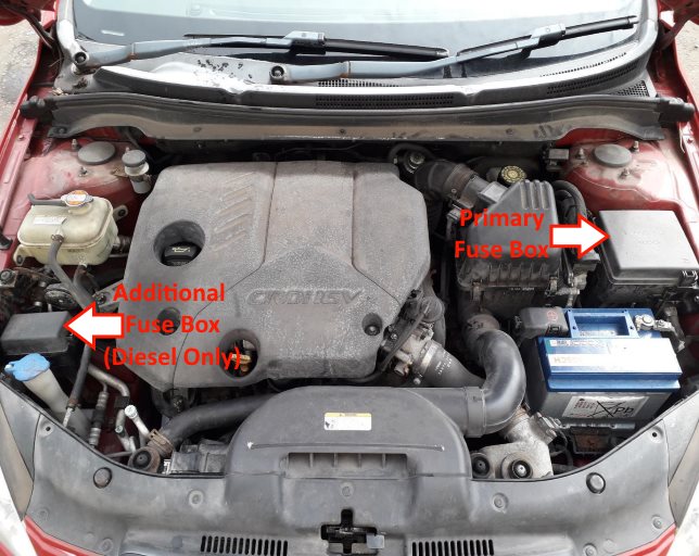
Location of components.
Main fuse box
The main distribution box is located behind the protective cover next to the battery.
Type 1
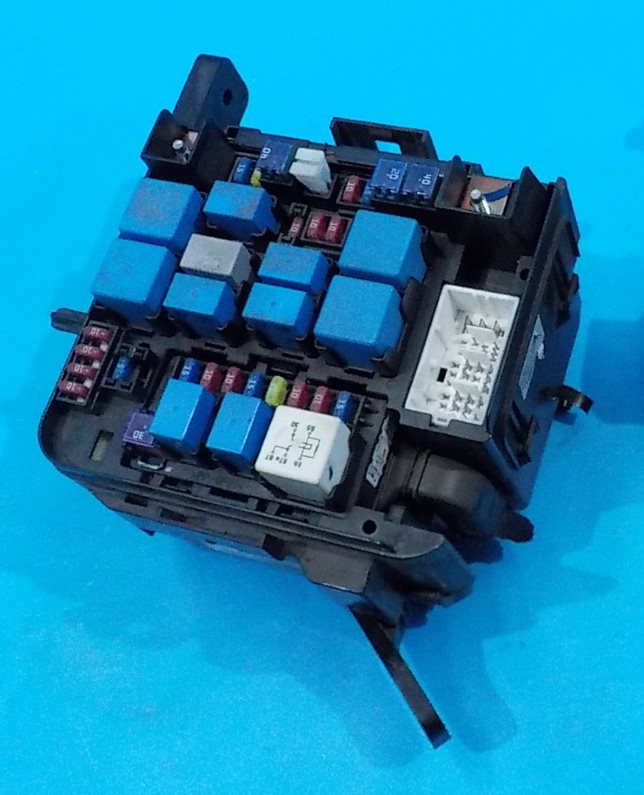
General view.
| Diagram | |
|---|---|
|
|
| № | Description |
| 1 | Main relay |
| 2 | Air conditioning |
| 3 | Fuel pump fuse |
| 4 | engine control module |
| 5 | ABS / ESP |
| 6 | Reversing lamp switch |
| 7 | Spare |
| 8 | Spare |
| 9 | Main relay |
| 10 | Spare |
| 11 | Sensors |
| 12 | engine control module |
| 13 | Sensors |
| 14 | Spare |
| 15 | Fuel injectors, air conditioning system. |
| 16 | Air conditioning |
| 17 | engine control module |
| 18 | Fuel pump |
| 19 | Electro fan |
| 20 | High beam relay |
| 21 | Sound signal |
| 22 | High fan speed |
| 23 | Starter relay |
| 24 | Rear fog lamsp |
| 25 | Glass cleaner |
| 26 | Low fan speed |
| 27 | Low beam left side |
| 28 | Low beam right side |
| 29 | Spare |
| 30 | Low beam relay |
| 31 | ABS / ESP |
| 32 | ABS / ESP |
| 33 | Front fog lights |
| 34 | Spare |
| 35 | Electronics unit salon |
| 36 | Spare |
| 37 | Buzzer relay |
| 38 | Electric power steering (ESP) |
| 39 | Starter and ignition switch |
| 40 | Heated mirrors |
| 41 | Fan (air conditioner) |
| 42 | Electro fan |
| 43 | Generator |
| 44 | Egnition lock |
| 45 | Electro interior control unit |
| 46 | Spare |
Example diagram from the block cover..
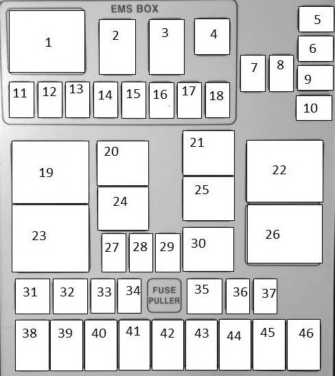
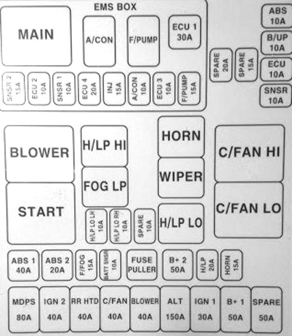
Type 2

General view.
| Diagram | ||
|---|---|---|

|
||
| № | Legend | Amps |
| 1 | ABS and ESP - ABS2 | 20 |
| 2 | ABS and ESP | 40 |
| 3 | Electronic control unit for electrical equipment of the passenger compartment - B + 1 | 50 |
| 4 | Heated mirrors - RR HTD | 40 |
| 5 | Electro fan - BLOWER | 40 |
| 6 | Electro Air Conditioning Fan - C / FAN | 40 |
| 7 | Headlight washer - H / LP WASHER | 20 |
| 8 | Spare | 20 |
| 9 | ALTERNATOR | 125 |
| 10 | Electro power steering - (Motor Driven Power Steering) | 80 |
| 11 | Front fog lamps - FR FOG | 15 |
| 12 | Air Conditioning - A / CON | 10 |
| 13 | Emergency signaling - HAZARD | 15 |
| 14 | Spare | 10 |
| 15 | Spare | 20 |
| 16 | Kia Ceed Fuel pump fuse - F / PUMP | 15 |
| 17 | Spare | 15 |
| 18 | Engine control unit - ECU1 | 10 |
| 19 | Engine control unit - ECU2 | 10 |
| 20 | Engine control unit - ECU3 | 20 |
| 21 | Fuel injectors, air conditioning - INJ | 15 |
| 22 | Sensors - SNSR2 | 10 |
| 23 | Sound signal - HORN | 15 |
| 24 | Electronic control unit for electrical equipment of the passenger compartment - B + 2 | 50 |
| 25 | Starter, ignition switch (lock) - ING2 | 40 |
| 26 | Ignition switch (lock) - IGN1 | 30 |
| 27 | Main relay - ECU | 30 |
| 28 | Stability control system ESP, anti-lock brake system ABS, exchange rate sensor - ABS | 10 |
| 29 | Ignition system - ECU2 | 10 |
| 30 | Reversing light switch - B / UP | 10 |
| 31 | Right headlight low beam - H / LP LO RH | 10 |
| 32 | Left headlight low beam - H / LP LO LH | 10 |
| 33 | High beam headlights - H / LP HI | 20 |
| 34 | Sensors - SNSR1 | 10 |
| R1 | C / FAN2 - Cooling fan relay (low speed) | |
| R2 | C / FAN1 - Cooling fan relay (high speed) | |
| R3 | Starter relay - START | |
| R4 | F / PUMP - Fuel Pump Relay | |
| R5 | A / CON - Air conditioner relay | |
| R6 | Headlamp low beam relay - H / LP LO | |
| R7 | Horn relay - HORN | |
| R8 | H / LP HI - Headlamp High Beam Relay | |
| R9 | Rear fog lamp relay - FOG LP | |
| R10 | Wiper relay - WIPER | |
| R11 | Main relay - MAIN | |
Additional distribution box

Installed on vehicles with diesel engine.
| Diagram |
|---|

|
| Legend |
| 12 - fuel filter heater relay |
| 13 - PTC heater #3 |
| 14 - PTC heater #2 |
| 15 - PTC heater #1 |
| 16 - glow plug relay |
In the passenger compartment
There are two distribution boxes here that are responsible for protecting the electrical circuits.
Fuse box
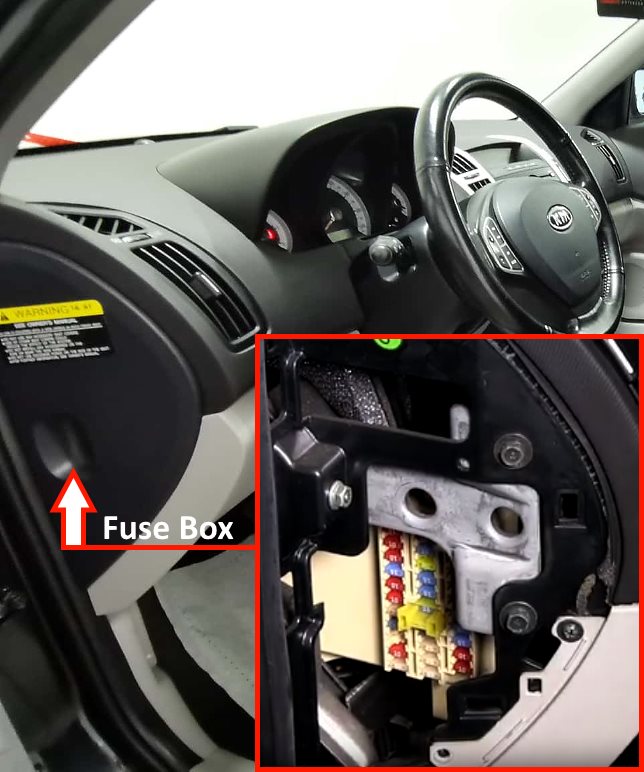
Located in the left end of the dashboard behind the protective cover.

General view of the KIA Ceed interior fuse box.
| Diagram | ||
|---|---|---|

|
||
| № | Legend | Amps |
| 1 | Starter relay - START | 10 |
| 2 | Air conditioning control unit - A / CON SW | 10 |
| 3 | Heated exterior mirrors - HTD MIRR | 10 |
| 4 | Seat heating - SEAT HTR | 15 |
| 5 | Air Conditioning - A / CON | 10 |
| 6 | High beam lamps - HEAD LAMP | 10 |
| 7 | Windshield wiper - FR WIPER | 25 |
| 8 | Tailgate wiper - RR WIPER | 15 |
| 9 | Inclusion of low beam headlights in the daytime - DRL OFF | 15 |
| 10 | Rear fog lamps - RR FOG | 10 |
| 11 | Left power window ontrol unit - P / WDW LH | 25 |
| 12 | Clock - CLOCK | 10 |
| 13 | Kia Ceed Cigarette lighter fuse | 15 |
| 14 | Sunroof, ignition control unit relay - DR LOCK | 20 |
| 15 | Windshield heater relay - DEICER | 15 |
| 16 | Stop lights - STOP | 15 |
| 17 | Interior lighting - ROOM LP | 15 |
| 18 | Audio system, trip computer - AUDIO | 15 |
| 19 | Rear 5th door - T / LID | 15 |
| 20 | Locking power windows (right side) - SAFETY P / WDW RH | 25 |
| 21 | Blocking power windows (left side) - SAFETY P / WDW LH | 25 |
| 22 | Power Windows - P / WDW | 25 |
| 23 | Power Outlet - P / OUTLET | 15 |
| 24 | Switch Block - T / SIG | 10 |
| 25 | Airbag Warning Lamp - A / BAG IND | 10 |
| 26 | Instrument panel - CLUSTER | 10 |
| 27 | Safety Airbags - A / BAG | 15 |
| 28 | Door or ignition control unit - IGN1-A | 15 |
| 29 | Front Power Outlet - RR P / OUTLET | 15 |
| 30 | Rear right marker lamp - TAIL RH | 10 |
| 31 | Rear left marker light - TAIL RH | 10 |
Relays
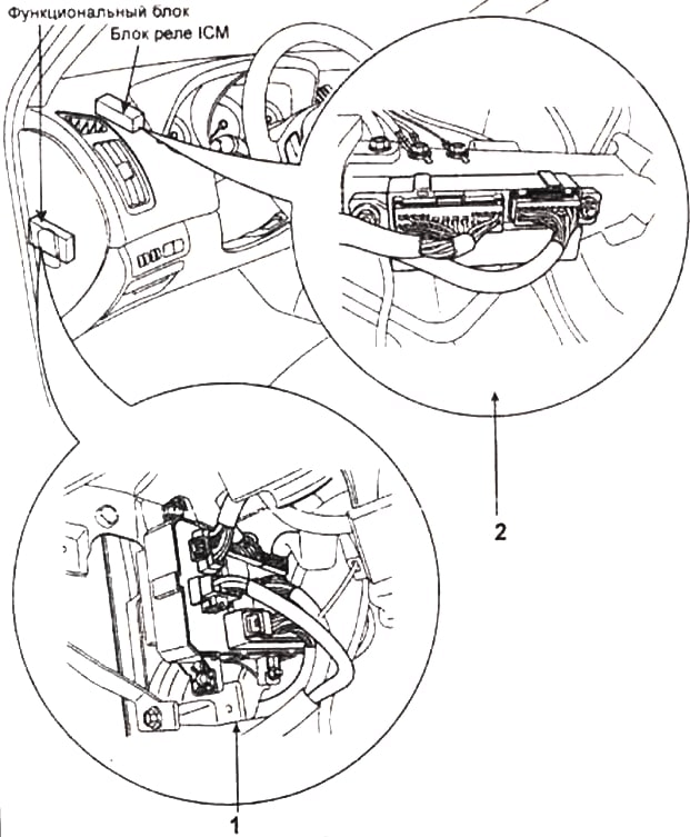
Location of relays in blocks
- 1 - rear light relay, heater relay, power window relay, tailgate relay;
- 2 (Built-in-ICM relay box) - windscreen defrost relay, central locking relay, rear fog lamp relay, anti-theft alarm horn relay, rain sensor relay.
Location of all units
General arrangement of electronic units and components..

| № | Description |
| 1 | ABS electronic control unit |
| 2 | Air conditioning electronic control unit - in the air conditioning / heater control panel |
| 3 | Sunlight sensor (air conditioning) (with automatic light control) |
| 4 | Air conditioning / heater blower motor control unit - next to blower motor |
| 5 | Air conditioner / heater blower motor relay |
| 6 | Air purity sensor |
| 7 | Impact sensor, left |
| 8 | Shock sensor, right |
| 9 | Side impact sensor, left - top of the B-pillar |
| 10 | Side impact sensor, right - top of the B-pillar |
| 11 | Anti-theft alarm sound |
| 12 | Generator excitation resistor |
| 13 | Battery |
| 14 | Cruise control control unit (cruise control) |
| 15 | Diagnostic connector (DLC) |
| 16 | Power window relay - in the under-dash fuse / relay box |
| 17 | Electronic engine control unit |
| 18 | Fuse / relay box, engine compartment 1 |
| 19 | Fuse / relay box, engine compartment 2 (Diesel) |
| 20 | Fuse / relay box, instrument panel |
| 21 | Heated rear window relay - in the under-dash fuse / relay box |
| 22 | Horn (top) |
| 23 | Horn (bottom) |
| 24 | Electronic immobilizer control unit (Diesel) |
| 25 | Immobilizer ring antenna - near the ignition switch |
| 26 | Instrument Cluster Illumination Rheostat Relay (with Daytime Lighting System) - In the under-dash fuse / relay box |
| 27 | Instrument cluster control unit |
| 28 | Multi-function switch control unit |
| 29 | Multifunction control unit - functions: Anti-theft system, central locking, daytime running lights, power windows, warning lights, headlights, heated rear window, heated windshield, interior lighting, seatbelt monitoring, rear light relay, windshield wiper/washer |
| 30 | Ambient temperature sensor - 1 |
| 31 | Ambient temperature sensor - 2 |
| 32 | Parking system control unit - behind the right rear trim panel |
| 33 | Parking system buzzer |
| 34 | Power steering control unit |
| 35 | Rain sensor |
| 36 | Rear Wiper Relay - Behind Left Rear Trim Panel |
| 37 | Relay unit - Functions: Anti-theft alarm siren, central locking, heated windshield, fog lights, rain sensor |
| 38 | Fixed power supply (stop-start system) |
| 39 | Seat heating control unit, left - under the seat |
| 40 | Seat heating control unit, right - under the seat |
| 41 | Brake light failure control unit - behind the right rear trim panel |
| 42 | Sunroof electric control unit |
| 43 | SRS electronic control unit |
| 44 | Tailgate Relays - In the under-dash fuse / relay box |
| 45 | Tailgate Actuator Relay - In the under-dash fuse / relay box |
| 46 | Electronic gearbox control unit |
| 47 | Selector and / or ignition key lock control unit |
| 48 | Tire pressure monitor control unit |
| 49 | Displacement / acceleration sensor |
