
The Kia Forte—known as the K3 in South Korea and Vietnam, the Forte K3 or Shuma in China, and the Cerato in South America, Australia, New Zealand, and Russia—is a compact car produced by the South Korean automaker since 2008, replacing the Spectra. In this article, we provide detailed fuse box diagrams and terminal assignments for the second-generation Kia Forte / Cerato (TD series) for model years 2008, 2009, 2010, 2011, 2012, and 2013.

Here you will find the locations, diagrams, and photos of the power distribution boxes. Fuses responsible for the “Cigarette Lighter” and “Fuel Pump” are highlighted in bold.
In the Engine Compartment

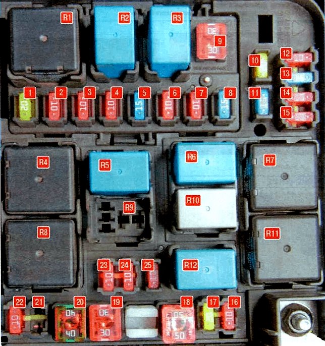
Located next to the battery on the left side of the engine bay. Remove the protective plastic cover to access it.
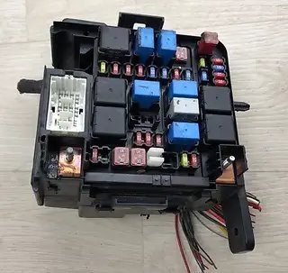
General view.
| Diagram | ||
|---|---|---|
|
||
| No. | Circuit Protected | Rating (A) |
| 1 | Ignition coils, ignition capacitor – IGN COIL | 20 |
| 2 | Engine control system sensors – SNSR2 | 10 |
| 3 | Engine control unit / Ignition system – ECU2 | 10 |
| 4 | A/C system, fuel injectors – INJECTOR | 10 |
| 5 | Engine control system sensors – SNSR1 | 15 |
| 6 | Main relay – ECU1 | 10 |
| 7 | Air conditioning system – A/CON | 10 |
| 8 | Kia Forte fuel pump fuse – F/PUMP | 15 |
| 9 | Engine Control Module (ECM) main relay – ECU | 30 |
| 10 | Spare | 20 |
| 11 | Spare | 15 |
| 12 | Reverse light switch – B/UPLP | 10 |
| 13 | Ignition coils, ignition capacitor – ECU3 | 15 |
| 14 | Electronic Stability Control (ESC), Anti-lock Braking System (ABS), yaw rate sensor – ABS | 10 |
| 15 | Engine control system sensors – SNSR3 | 10 |
| 16 | Horn – HORN | 10 |
| 17 | Headlamp high beam – H/LP HI | 20 |
| 18 | Body Control Module (BCM) / Cabin electronics – BATT2 | 50 |
| 19 | Ignition switch – IGN 1 | 30 |
| 20 | Electronic Stability Control (ESC), Anti-lock Braking System (ABS), Diagnostic Link Connector (DLC) – ABS1 | 40 |
| 21 | Spare | 20 |
| 22 | Front fog lamps, Diagnostic Link Connector (DLC) – FOG LP (FR) | 10 |
| 23 | Left low beam headlamp – H/LP LO LH | 10 |
| 24 | Right low beam headlamp – H/LP LO RH | 10 |
| 25 | Spare | 10 |
| No. | Relay Assignment | |
| 1 | Main relay | |
| 2 | Fuel pump relay | |
| 3 | A/CON – Air conditioner compressor relay | |
| 4 | BLOWER – Blower motor / Radiator cooling fan relay | |
| 5 | H/LP HI – Headlamp high beam relay | |
| 6 | HORN – Horn relay | |
| 7 | C/FAN HI – Radiator cooling fan relay (high speed) | |
| 8 | START – Starter motor relay | |
| 9 | FOG LP – Rear fog lamp relay | |
| 10 | WIPER – Windshield wiper relay | |
| 11 | C/FAN LO – Radiator cooling fan relay (low speed) | |
| 12 | H/LP LO – Headlamp low beam relay | |
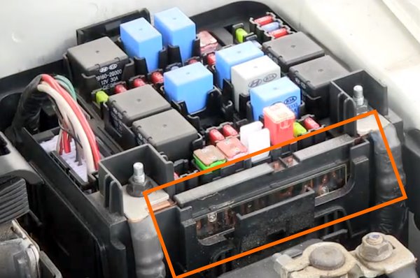
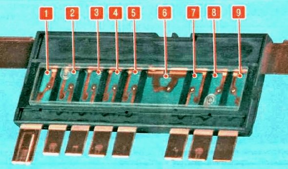
Mounted on the side wall of the engine compartment fuse box is the main high-current fuse panel.
| Diagram | ||
|---|---|---|
|
||
| No. | Circuit Protected | Rating (A) |
| 1 | Motor-Driven Power Steering (MDPS) / EPS control unit | 80 |
| 2 | ABS2 – ABS / ESC control unit | 40 |
| 3 | C/FAN – Electric cooling fan | 40 |
| 4 | BLOWER – Climate control blower motor | 40 |
| 5 | HTD GLASS – Heated rear window & door mirrors | 40 |
| 6 | ALT – Alternator | 125 |
| 7 | IGN2 – Ignition switch | 30 |
| 8 | BATT 1 – Body Control Module (BCM) / Cabin electronics | 50 |
| 9 | Spare | 50 |
In the Passenger Compartment
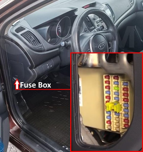
Located on the driver’s side at the end panel of the dashboard.
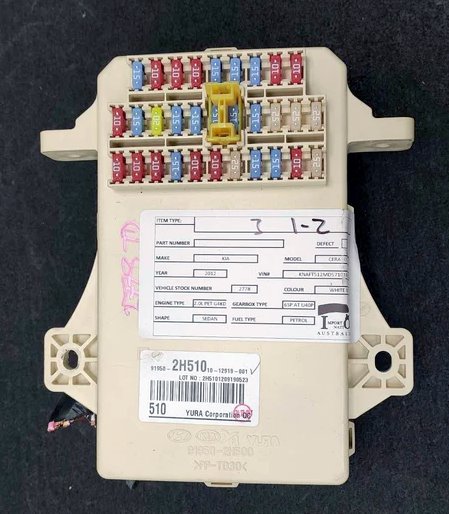
Overview of the Kia Forte / Cerato (TD) interior passenger compartment fuse box.
| Diagram | ||
|---|---|---|
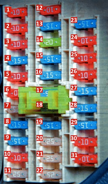
|
||
| No. | Circuit Protected | Rating (A) |
| 1 | Starter relay, anti-theft alarm module – START | 10 |
| 2 | A/C control panel switch – A/CON SW | 10 |
| 3 | Heated exterior mirrors – HTD MIRR | 10 |
| 4 | Heated seats – SEAT HTR | 15 |
| 5 | Air conditioning control module – A/CON | 10 |
| 6 | Headlamp circuit – HEAD LAMP | 10 |
| 7 | Front windshield wipers – FR WIPER | 25 |
| 8 | Rear window wiper / Spare | 10 / 15 |
| 9 | Smart Key module, door lock control unit – DRL / SMK | 15 |
| 10 | Rear fog lamps – RR FOG | 10 |
| 11 | Driver-side power window control unit – P/WDW DR | 25 |
| 12 | Digital clock, display – D CLOCK | 10 |
| 13 | Kia Forte cigarette lighter fuse – CIGAR LIGHTER | 15 |
| 14 | Sunroof, door lock relay – DR LOCK | 20 |
| 15 | Windshield wiper de-icer relay – DEICER | 15 |
| 16 | Brake lamps (stop lights) – STOP LP | 15 |
| 17 | Interior cabin lighting – ROOM LP | 15 |
| 18 | Audio system, head unit, trip computer – AUDIO | 15 |
| 19 | Trunk release actuator relay – TRUNK OPEN | 15 |
| 20 | Passenger door module – PDM | 25 |
| 21 | Power window safety lock switch – SAFETY P/WDW | 25 |
| 22 | Passenger power windows – P/WDW ASS | 25 |
| 23 | 12V Auxiliary power outlet – P/OUTLET | 15 |
| 24 | Turn signal lamps, flasher module – T/SIG LP | 10 |
| 25 | Airbag warning indicator – A/BAG IND | 10 |
| 26 | Instrument cluster – CLUSTER | 10 |
| 27 | Supplemental Restraint System (SRS) airbags – A/BAG | 15 |
| 28 | Door lock and ignition switch control unit – IGN1-A | 15 |
| 29 | Hazard warning flasher relay – HAZARD LP | 15 |
| 30 | Right rear tail lamp – TAIL LP (RH) | 10 |
| 31 | Left rear tail lamp – TAIL LP (LH) | 10 |

why some fuses are placed up side down????
it works either way