The Kia Forte, known as K3 in South Korea and Vietnam, Forte K3 or Shuma in China and Cerato in South America, Australia, New Zealand, is a compact car produced by the South Korean automaker since mid-2003. On 15 January 2018, Kia unveiled the third-generation Forte sedan at the 2018 North American International Auto Show in Detroit, Michigan. In this article, we will take a detailed look at the fuse box diagrams for the Kia Forte / Cerato (3gen; YD index) 2012, 2013, 2014, 2015, 2016, 2017 and 2018 years of manufacture.

Here you will find the locations and photos of distribution boxes. The fuses responsible for the “Cigarette lighter” and “Fuel Pump” are highlighted in bold.
In the engine compartment
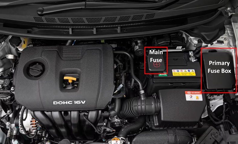
Location of components.
Main fuse
Located on the positive terminal of the battery.

Description:
- AMS - Battery sensor 7.5A;
- ALT - Alternator 150A
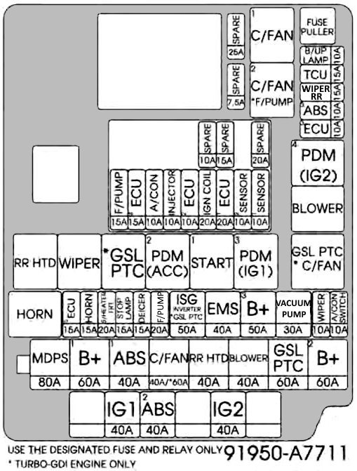
Primary fuse box
It is located behind the plastic cover on the left side.
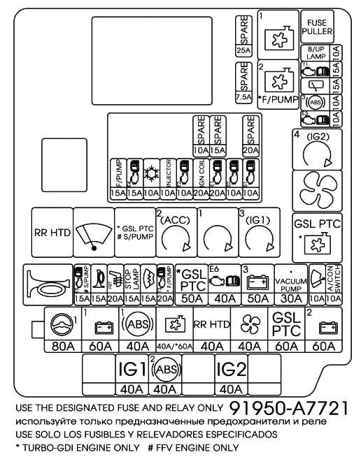
Example of a schematic from the block cover.
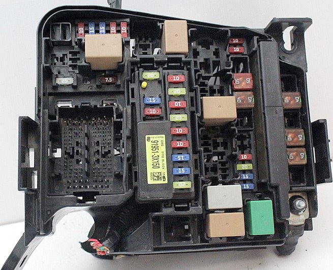
General view.
| Diagram | ||
|---|---|---|
|
||
| № | Description | A |
| B + 1 | Intelligent distribution box (ARISU-LT IPS 1 (4СН), ARISU-LT IPS 2 (4СН)), Fuse - left power window 25A, right power window 25A, trunk 10A, module6 7.5 A, module7 10A) | 60 |
| C / FAN | Cooling fan relay, low, cooling fan relay | 60 |
| B + 2 | Intelligent Junction Box (ARISU-LT IPS 4 (4CH), ARISU-LT IPS 3 (4CH), IPS 5 (2CH)), Fuse - Power Seat (Driver), Brake Switch, PDM1, Rear Seat Heater | 60 |
| GSLRTS | Gasoline relay with PTC | 60 |
| ABS3 | ABS: ABS control unit ESC: ESC control unit, yaw rate sensor | 10 |
| A / CON SW | A / C ECU, Blower Motor, A / C Resistor | 10 |
| B + 3 | Intelligent Junction Box (Automatic Leakage Cut-off Device, Fuses - PDM2, Door Lock, Sunroof) | 50 |
| BACK-UP | automatic transmission: electrochromic mirror, audio-visual head unit with navigation, rear combination light (interior), rearview camera Manual transmission: reversing light switch |
10 |
| LAMP | ||
| STOP LP | Stop signals | 15 |
| FUEL PUMP | Kia Forte fuel pump fuse | 15 |
| INJECTOR | Injector No. 1 / No. 2 / No. 3 / No. 4, fuel pump relay, air conditioning compressor relay | 10 |
| ECU 2 | Engine control module | 10 |
| IGN COIL 1 | Ignition coil, capacitor | 20 |
| ECU 1 | Engine control module | 20 |
| SENSOR 2 | Oxygen sensor (upper / lower), variable geometry solenoid valve, #1 / #2 oil pressure regulator, purge control solenoid valve, cooling fan relay | 10 |
| SENSOR 1 | Camshaft position sensor No. 1 / No. 2 | 10 |
| A / CON COMP | A / C compressor relay | 10 |
Additional distribution box
Installed on diesel engine vehicles on the right side of the underhood.

Description:
- PTC HEATER - auxiliary heater.
- 80A - glow plug fuse.
In the passenger compartment
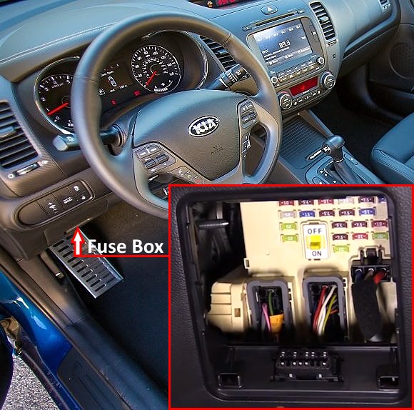
Located on the driver's side under the dashboard. Remove the plastic cover to access it.
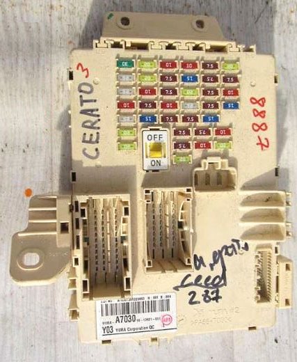
General view of the Kia Forte / Cerato interior fuse box.
| Diagram | ||
|---|---|---|

|
||
| № | Legend | A |
| 1 | POWER SEAT DRIVER - Driver's seat unit (power seat, lumbar support) | 30 |
| 2 | SPARE | 25 |
| 3 | POWER WINDOW RH - Intelligent distribution box (power window relay, right) | 25 |
| 4 | TRUNK - Intelligent Junction Box (Trunk Lid Relay) | 10 |
| 5 | POWER WINDOW LH - Intelligent distribution box (power window relay, left) | 20 |
| 6 | DOOR LOCK - Intelligent distribution box (door lock relay, door unlock relay) | 20 |
| 7 | SPARE | 20 |
| 8 | Kia Forte / Cerato cigarette lighter fuse and power outlet | 20 |
| 9 | SEAT HEATER REAR - spare | 20 |
| 10 | MODULE8 - ВСМ, ECU of electronic keys | 10 |
| 11 | SPARE | 7.5 |
| 12 | SPARE | 15 |
| 13 | MODULE1 - electronic keys ECU, VSM, digital clock, audio system, audiovisual head unit with navigation, electric control of external mirrors | 10 |
| 14 | AIR CON - air conditioning ECU, ionizer on the instrument cluster, Fan relay, petrol relay with PTC | 7.5 |
| 15 | MODULE5 - Roof hatch, driver's seat CCS ECU, passenger seat heater module, rear seat heater | 7.5 |
| 16 | HEATED MIRROR - ECM, A / C ECU, outside mirror | 10 |
| 17 | INTERIOR LAMP - trunk light, driver's side directional light, passenger's side directional light, glove box light, left/right sun visor, interior courtesy light, roof console light, ignition switch light and door sensor light (without electronic keys) | 7.5 |
| 18 | MODULE6 - Sport Mode Switch, Key Lock | 7.5 |
| 19 | PDM2 - "With electronic keys: ECU of electronic keys Without electronic keys: Immobilizer module" | 7.5 |
| 20 | SUNROOF | 20 |
| 21 | MODULE2 - Electrochromic rearview mirror, multifunctional diagnostic connector, headlight range control, A/C ECU, left/right headlight range control, driver CCS ECU, driver IMS module, passenger seat heating module | 10 |
| 22 | HEATED STEERING - Heated steering wheel | 15 |
| 23 | IG1 - Without electronic keys: relay and fuse box for the engine compartment (fuse - BUT 1, ECU 3, ABS 3) | 20 |
| 24 | WIPER FRONT - Windshield wiper motor, under-hood fuse / relay box (wiper relay), multifunction switch | 25 |
| 25 | SPARE | 7.5 |
| 26 | MEMORY - Driver IMS module, driver's side external electronic key handle, passenger's side external electronic key handle, BCM, tire pressure monitoring module, automatic light sensor and photocell, instrument cluster, Data Link connector, multifunctional diagnostic connector, digital clock, air conditioning ECU | 7.5 |
| 27 | MODULE7 - ICM relay box, (turn signal horn relay, folding mirror relay, folding mirror relay) | 10 |
| 28 |
|
7.5 |
| 29 | Motor Driven Power Steering - EUR ECU | 7.5 |
| 30 | MODULE3 - Dashboard | 7.5 |
| 31 | START - With burglar alarm, without electronic keys and without immobilizer: ICM relay box (burglar alarm relay) Without burglar alarm, with electronic keys or with immobilizer: transmission range selector switch (automatic transmission), engine compartment fuse and relay box (starter relay), electronic key ECU, ECM " |
7.5 |
| 32 | MULTIMEDIA1 - Audio system, audiovisual head unit with navigation | 15 |
| 33 | BRAKE SWITCH - Brake light switch | 10 |
| 34 | PDM1 - Electronic key ECU | 20 |
| 35 | POWER OUTLET FRT - Front power socket | 20 |
| 36 | A / BAG IND - Dashboard | 7.5 |
| 37 | MODULE4 - front panel switch, tire pressure monitor module, brake light switch, digital clock, BCM, rear left parking sensor (external/internal), right parking sensor (external/internal), left/right front parking sensor | 10 |
| 38 | A / BAG - SRS ECU | 15 |

The relay unit is located under the panel in a single junction box of the integration modular electrical circuit.
Depending on the vehicle configuration, the following relays may be located here:
- power mirrors;
- window heating;
- illumination;
- windshield wiper;
- keyless access system;
- power windows;
- alarm system;
- TFT LCD 4.2 ";
- and other controls
