Table of Contents
In this article, we will take a detailed look at the fuse diagrams for the Lincoln Navigator (first generation; un173): 1997, 1998 release.

Fuses #3 in the engine bay block and #10, #11 in the interior block are responsible for the cigar lighter and power outlets.
In the engine compartment
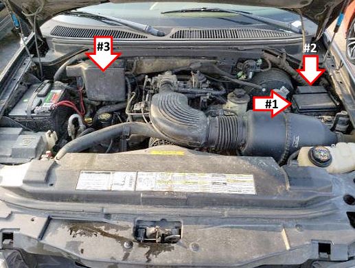
Location of the components:
1. Main fuse block,
2. Additional fuse panel,
3. Power fuse box.
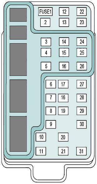
Main fuse block
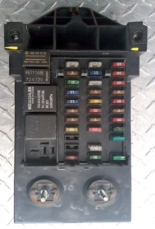
General view.
| Diagram | ||
|---|---|---|
|
||
| No. | Description | Amps |
| 1 | Flasher Relay (Turn/Hazard) | 15 A |
| 2 | Redundant Steering Control Unit, Overhead Trip Computer (OTC), Instrument Cluster, Automatic Temperature Control (EATC) Unit, Clock | 5 A |
| 3 | Lincoln Navigator Cigarette Lighter Fuse | 25 A |
| 4 | Headlamps, Park Lamps, Remote Anti-theft Personality (RAP), Autolamp Unit, Memory Seat and Mirror, Power Mirror Switch, Memory Seat Switch, Driver Power Seat Control Switch | 5 A |
| 5 | Speed Control Servo/Amplifier Assembly, Daytime Running Lamps (DRL) Module, Digital Transmission Range (DTR) Sensor, EATC Clutch Relay | 15 A |
| 6 | Generic Electronic Module (GEM), Shift Lock Actuator, Compass Sensor, 4 Wheel Air Suspension 4WAS Module, Heated Grid Relay, Steering Wheel Rotation Sensor, Overhead Trip Computer (OTC) | 5 A |
| 7 | Console Blower Motor / Auxiliary A/C Relay | 5 A |
| 8 | Main Light Switch, Radio, Generic Electronic Module (GEM), Remote Anti-theft Personality (RAP), Ignition Switch, Clock | 5 A |
| 9 | Empty | — |
| 10 | Empty | — |
| 11 | Wiper Run/Park Relay / Washer Pump Relay | 30 A |
| 12 | DLC - Data Link Connector | 5 A |
| 13 | Brake Pressure Switch / Brake On/Off (BOO) Switch | 15 A |
| 14 | Interior Lamp Relay / Battery Saver Relay | 15 A |
| 15 | SecuriLock and Generic Electronic Module (GEM) | 5 A |
| 16 | Daytime Running Lamps (DRL), Instrument Cluster (W/O DRL), Hi-Beam Headlamps | 20 A |
| 17 | Left and Right Power/Heated Signal Mirror / Heated Backlite Switch | 10 A |
| 18 | Generic Electronic Module (GEM), Instrument panel Illumination, Main Light Switch, Park Lamp Relay, Trailer Electronic Brake Control, Left and Right Side Marker Lamps, Trailer Tow Running Lamp Relay, Front Park/Turn Lamps, Left and Right Stop/Park/Tum Lamp, Left and Right License Lamp | 5 A |
| 19 | Air Bag Diagnostic Monitor, Instrument Cluster | 10 A |
| 20 | Memory Seat and Mirror Module / 4 Wheel Air Suspension 4WAS Generic Electronic Module (GEM) | 5 A |
| 21 | Junction Box Fuse/Relay Panel (Fuse #20) / Digital Transmission Range (DTR) Sensor | 15 A |
| 22 | Ignition Switch and Air Bag Diagnostic Monitor | 10 A |
| 23 | Auxiliary A/C Mode Actuator - A/C Control Module and A/C Blend Actuator Flasher Relay, Trailer Tow Battery Charge Relay, 4X2 and 4X4 Center Axle Disconnect Solenoid, Rear Integrated Control Panel, Electronic Day/Night Mirror | 10 A |
| 24 | Automatic Temperature Control (ATC), Auxiliary A/C Relay, Console Blower Relay | 10 A |
| 25 | 4 Wheel Anti-Lock Brake System (4WABS) | 5 A |
| 26 | Right Headlamp (Power supplied through Multi-Function Switch) and DRL - Daytime Running Lamps | 10 A |
| 27 | Fog Lamp Relay / Main Light Switch | 5 A |
| 28 | Left Headlamp | 10 A |
| 29 | Instrument Cluster, Autolamp Module, Transmission Control Switch (TCS) | 5 A |
| 30 | SecuriLock, Radio Noise Capacitor, Coil on Plugs, PCM Power Diode, PCM Power Relay | 30 A |
| 31 | Empty | — |
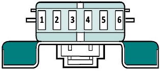
Additional fuse panel
Located near the main fuse box.
| Diagram | ||
|---|---|---|
|
||
| 1 | PCM - Powertrain | 5 A |
| 2 | Trailer Turn Lamps and Tow Stop Lamp | 20 A |
| 3 | Compact Disc Changer, Audio Rear Integrated Control Panel (RICP), Radio | 10 A |
| 4 | Running Board Lamps | 10 A |
| 5 | Subwoofer and Audio System Amplifier | 20 A |
| 6 | Empty | — |
Power fuse box

Located near the battery.
| Diagram | ||
|---|---|---|

|
||
| 1 | Megafuse - Power Network Box | 175 A |
| 2 | Megafuse - Alternator | 175 A |
| 3 | Field Minifuse - Alternator | 20 A |
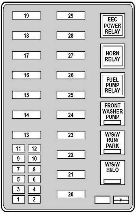
In the passenger compartment
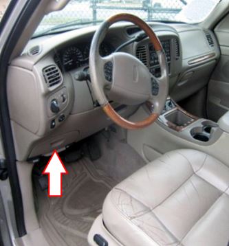
Fuse box located to the left and below of the steering wheel, behind the plastic cover.

General view.
| Diagram | ||
|---|---|---|
|
||
| No. | Description | Amps |
| 1 | Trailer Tow: Backup Lamp Relay and Running Lamp Relay | 20 A |
| 2 | Air Bags Diagnostic monitor | 10 A |
| 3 | Driver’s Unlock Relay, All Lock / Unlock Relay | 30 A |
| 4 | Air Suspension Service Switch | 15 A |
| 5 | Horn Relay | 20 A |
| 6 | Rear Integrated Control Panel, Radio, CD Changer, Premium Audio Amplifier, Sub-Woofer power | 30 A |
| 7 | Park Lamp Relay, Main Light Switch | 15 A |
| 8 | Headlamp Relay, Main Light Switch, Multi-Function Switch | 30 A |
| 9 | Fog Lamp Relay, DRL - Daytime running lamps | 15 A |
| 10 | I/P Auxiliary 12V Power Outlet | 25 A |
| 11 | Auxiliary 12V Power Outlet - Console | 25 A |
| 12 | Rear Wiper Up/Down Motor Relay | 10 A |
| 13 | A/C Relay - Auxiliary | 30 A |
| 14 | 4WABS - 4 Wheel Anti-Lock Brake System | 60 A |
| 15 | Air Suspension Solid State Compressor Relay | 50 A |
| 16 | Trailer Tow - Left and Right Turn Relay, Trailer tow - battery Charge Relay, fuse #2 in mini block | 40 A |
| 17 | Torque on Demand Relay / Transfer Case Shift Relay | 30 A |
| 18 | Memory Seat Module | 30 A |
| 19 | Lincoln Navigator Fuel Pump Relay | 20 A |
| 20 | Ignition Switch | 50 A |
| 21 | 50 A | |
| 22 | Junction Box Fuse/Relay Panel Battery Feed | 50 A |
| 23 | I/P Blower Relay | 40 A |
| 24 | PCM Power Relay, Powertrain Control Module, fuse #1 - Mini Fuse Block | 30 A |
| 25 | ACC Delay Relay, Junction Box Fuse/Relay Panel (Circuit Breaker) | 30 A |
| 26 | Passenger Power Seat Control Switch | 30 A |
| 27 | Heated Grid Relay, Junction Box Fuse/Relay Panel | 40 A |
| 28 | Trailer Electronic Brake Control | 30 A |
| 29 | Vent Window/Sunroof, RPO Relay Block | 30 A |
View and print PDF:
