Mazda Bongo (also E-Series and Access) is a van produced by the Japanese concern, starting in 1966. According to the location of the powertrain was produced as rear-engined, mid-engined and front-engined. In this article, we will take a detailed look at the fuse box diagrams for the Mazda Bongo - Friendee and Brawny (1st generation; codename SG) 1995, 1996, 1997, 1997, 1998, 1998, 1999, 2000, 2001, 2002, 2003, 2004, 2005 years of manufacture.

Here you will find the locations and photos of distribution boxes. The fuses responsible for the “Cigarette lighter” and “Fuel Pump” are highlighted in bold.
There is no one common scheme for all Mazda Bongo models. Check the assignment of elements with their schemes on the back of the protective covers.
Type 1
In the engine compartment
A separate fuse box and a separate relay box are located here.
Fuse box

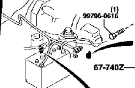
Placed near the battery. Remove the protective cover to access it.
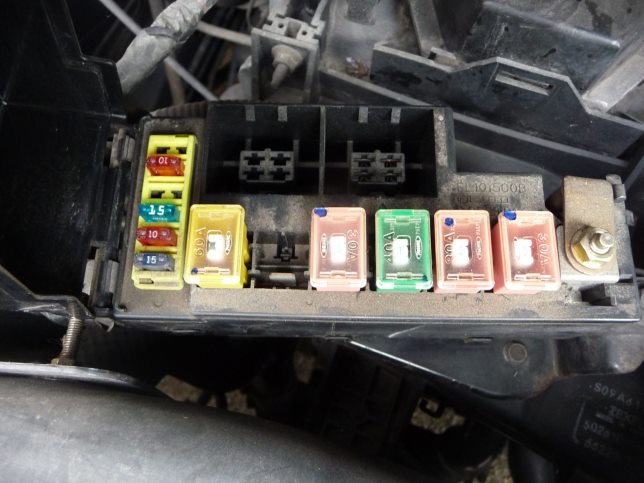
Access example.
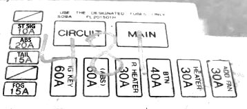
| Diagram | ||
|---|---|---|
|
||
| Code | Decoding | Amps |
| MAIN | Main fuse | 100 |
| HEAD | Headlights | 30 |
| FAN | Condenser fan motor, fuses for various circuits | 30 |
| FAN 2 | 40 | |
| ST SIG | Starter | 10 |
| PTC | Additional heater | 20 |
| ABS | Anti-lock brake system | 20 |
| TAIL | Side lights, dashboard illumination | 15 |
| AC POWER | Fuse for various circuits | 15 |
| FIP | fuel pump fuse, engine control unit | 15 |
| FOG | Fog lights | 15 |
| IGKEY | Fuse for various circuits | 60 |
| ABS | Anti-lock brake system | 60 |
| R.HEATER | Rear heater | 30 |
| BTN | Interior lighting, central locking | 40 |
| HEATER | Heater | 30 |
| ADD FAN | Condenser fan electric motor | 30 |
| Circuit | fuel pump relay | |
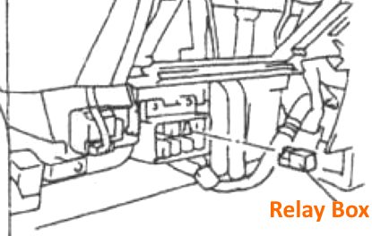
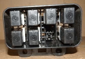
Relay unit
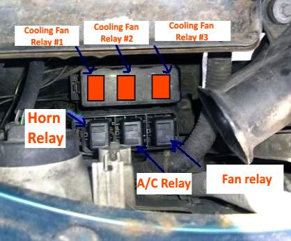
The unit with the relay modules is located near the main unit.
Some elements can be placed separately. For example, plug relay - near the battery, rear heater - near the heater. On the left fender: modules of parking light relays, fog lights relays, etc..
In the passenger compartment
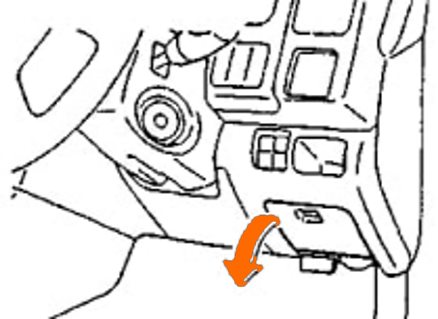
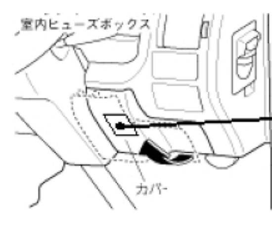
The distribution box is located at the bottom of the dashboard behind a plastic cover.

General view of the Mazda Bongo sg interior fuse box.
| Diagram | ||
|---|---|---|
|
||
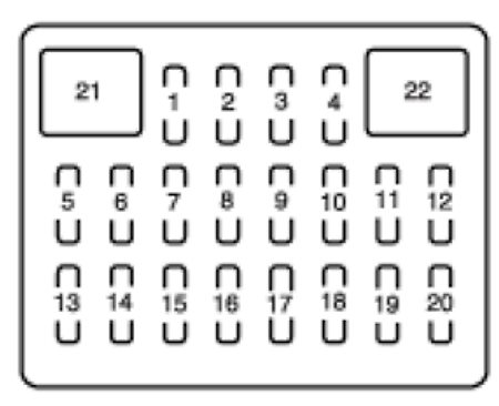
| No. | Description | Amps |
| 1 | HEAD R - Right headlight (models from 2001) | 20 |
| 2 | HEAD L - Left headlight (models from 2001) | 20 |
| 3 | Spark plugs (models from 1999) | 20 |
| HEAD HI - Headlights (models from 2001) | 20 | |
| 4 | CLOSER - Door closing system | 15 |
| 5 | A/C - Air conditioning | 10 |
| 6 | WIPER - Windshield wipers and washers | 20 |
| 7 | P/WIND - Power window actuator | 30 |
| 8 | R.WIPER - Rear Door Window Wiper | 10 |
| 9 | SUN ROOF - Sunroof, fuse for various circuits | 20 |
| 10 | TURN - Direction indicators | 10 |
| 11 | METER — Instrument Cluster | 15 |
| 12 | ENGINE - Engine management system | 15 |
| 13 | Bongo cigarette lighter fuse, power mirrors, audio system, fuse for various circuits, engine compartment fan | 15 |
| 14 | BLIND (RH) - Electric actuator of the right curtain | 15 |
| 15 | BLIND (RH) - Electric actuator of the left curtain | 15 |
| 16 | HORN - Horn (models from 1999) | 10 |
| TAIL - Parking lights, instrument cluster illumination (models from 2001) | 15 | |
| 17 | DOOR LOCK - Central locking | 30 |
| 18 | STOP - Stop lights | 15 |
| 19 | HAZARD - Hazard Alarm | 10 |
| 20 | ROOM - Interior lighting, luggage compartment lighting | 10 |
| 21 | DEFOGGER - Rear door window heater (models from 1999) | 30 |
| 22 | OPTION - Additional equipment (models from 1999) | 30 |
Type 2
Unit #1
The main distribution box is located under the driver's side under the dashboard, behind a plastic cover.
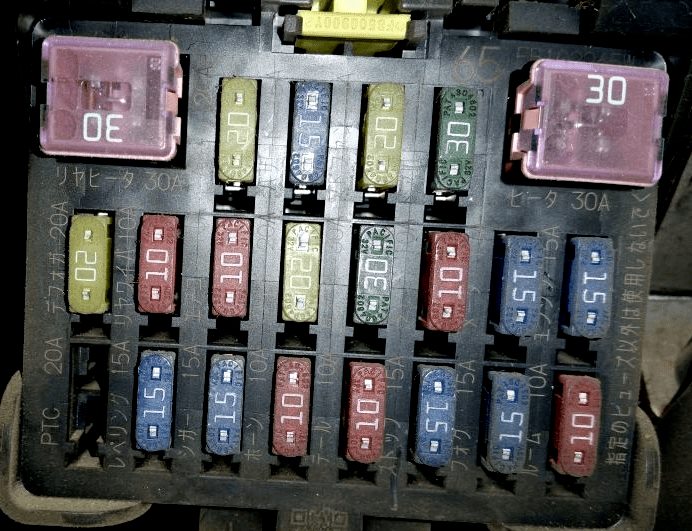
General view.
| Diagram | ||
|---|---|---|

|
||
| No. | Description | Amps |
| 1 | ABS brake system | 20 |
| 2 | Alarm | 15 |
| 3 | Spare | 20 |
| 4 | Electric central locking system | 30 |
| 5 | Rear door window heater | 20 |
| 6 | Rear door window wiper | 10 |
| 7 | Air conditioner | 10 |
| 8 | Windshield wipers and washers | 20 |
| 9 | Power windows | 30 |
| 10 | Direction indicators | 10 |
| 11 | Instrument cluster | 15 |
| 12 | The engine control unit | 15 |
| 13 | Fuel heater | 20 |
| 14 | Reserve | 15 |
| 15 | Cigarette lighter fuse | 15 |
| 16 | Horn | 10 |
| 17 | Tail lights | 10 |
| 18 | Stop signals | 15 |
| 19 | Fog lights | 15 |
| 20 | Interior lighting | 10 |
| 21 | Rear heater | 30 |
| 22 | Main heater | 30 |
Unit #2
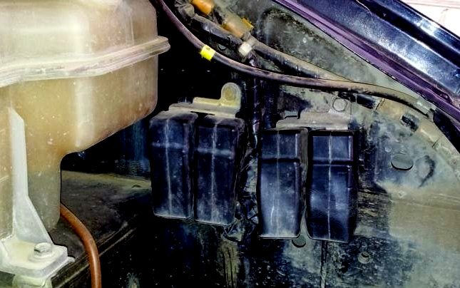
The auxiliary distribution box is located under the driver's seat, or between the battery and the engine in gasoline models, or under the passenger seat, or near the hydraulic system reservoir in diesel models.
| Diagram | ||
|---|---|---|

|
||
| No. | Decoding | Amps |
| 1 | HEAD - headlights | 30 |
| 2 | FIP/ INJ - engine control unit | 30 |
| 3 | GLOW - glow plugs | 60 |
| 4 | main fuse | 80 |
| 5 | ABS | 60 |
| 6 | KEY - fuse for various circuits | 40 |
| 7 | BTN - interior lighting, electrically operated central locking system | 60 |
Relay box
Under the glove box on the passenger side there is a block with relay modules.
Here you can find relay modules responsible for:
- Stop signals;
- Front and rear heater fans;
- Automatic transmission selector;
- Air conditioner;
- Headlights;
- Horn;
- Headlights;
- Automatic transmission selector.
