The Mazda 626 was based on the Capella model produced primarily for the Japanese market. It replaced the 616/618 and RX-2 models in 1979 and was produced until 2002. The car was presented in sedan, hatchback and station wagon bodies, and its basic version was characterized by a high level of comfort. In this article, we will take a detailed look at the fuse box diagrams for the Mazda 626 / Capella (5th generation; codename GF) 1997, 1998, 1999, 2000, 2001, 2003 years of manufacture.
Here you will find the locations and photos of distribution boxes. The fuses responsible for the “Cigarette lighter” and “Fuel Pump” are highlighted in bold.
In the engine compartment
There is one fuse box under the hood, as well as separate relay modules.
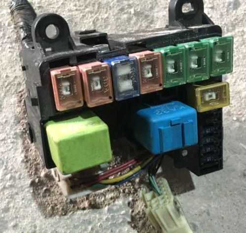
Primary fuse box
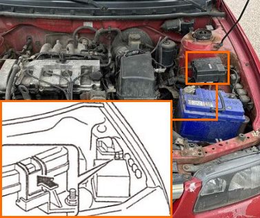
Located next to the battery, on the left side.
Version No. 1
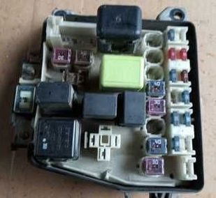
General view.
| Diagram | ||
|---|---|---|
|
||
| No. | Description | Amps |
| 1 | Condenser fan motor*, fuse for various circuits | 30 |
| 2 | Anti-lock braking system ABS*, fuse for various circuits | 60 |
| 3 | Fuse for various circuits | 40 |
| 4 | Not used | - |
| 5 | Interior lighting, central locking* | 40 |
| 6 | Heater | 40 |
| 7 | Cooling fan motor | 30 |
| 8 | Not used | - |
| 9 | Rear window / rear door window heater | 40 |
| 10 | Engine management system | 30 |
| 11 | Fog lights* | 15 |
| 12 | Not used | - |
| 13 | Horn | 10 |
| 14 | Alarm | 10 |
| 15 | Parking lights, instrument cluster illumination | 15 |
| 16 | Fuse for various circuits | 10 |
| 17 | Not used | - |
| 18 | Fuse for various circuits | 15 |
| 19 | Brake lights | 15 |
| 20 | Right headlight | 15 |
| 21 | Left headlight | 15 |
| 22 | Not used | - |
| 23 | ||
| 24 | Main fuse | 100 |
| Note : * - some models. | ||
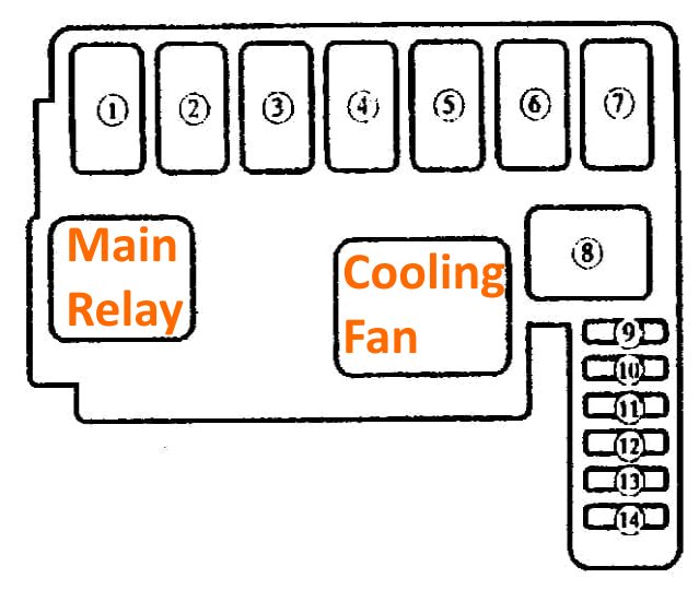
Version No. 2
General view.
| Diagram | ||
|---|---|---|
|
||
| No. | Decoding | Amps |
| 1 | Additional cooling fan for air conditioner | 30 |
| 2 | Fuel injection system /f uel pump fuse | 30 |
| 3 | For the protection of all electrical systems | 100 |
| 4 | Cooling Fan | 30 |
| 5 | Heater air conditioner | 40 |
| 6 | Fuses 2, 3, 4, 7, 10, 13, 14, 15 and 16 on the fuse panel | 40 |
| 7 | BTN - Fuses 6, 8, 9 and 11 on the fuse panel | 40 |
| 8 | ABS system | 60 |
| 9 | Rear lights, parking lamps | 15 |
| 10 | Hazard warning lights, direction indicators | 15 |
| 11 | Brake lights | 15 |
| 12 | Front fog lights | 15 |
| 14 | Headlights (dipped beam) | 15 |
| 15 | Headlights (high beam) | 15 |
| - | MAIN RELAY - Main relay | |
| - | COOLING FAN - Cooling fan relay | |
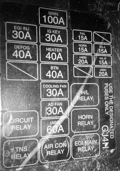
Version No. 3
General view.
| Diagram | ||
|---|---|---|
|
||
| Code | Purpose | Amps |
| EGI INJ | Fuel injection system | 30 |
| DEFOG | Heated rear window | 40 |
| MAIN | Common to all equipment | 100 |
| IG KEY | radio, sunroof, turn signals, engine electrics, power windows, ignition system | 30 |
| HEATER | stove, air conditioner | 40 |
| BTN | door locks, power seats | 40 |
| COOLING FAN |
cooling Fan | 30 |
| AD FAN | additional cooling fan | 30 |
| ABS | ABS brakes | 60 |
| TAIL | tail lights, parking lights, dashboard lighting, license plate lighting, light switches | 15 |
| HORN | sound signal | 15 |
| ABS | ABS | 20 |
| H/LL | left headlight | 15 |
| H/LR | right headlight | 15 |
| AIR CON RELAY |
Air conditioner relay | |
| HORN RELAY |
Horn relay | |
| H/L RELAY |
Headlight relay | |
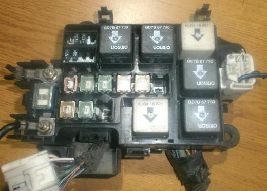
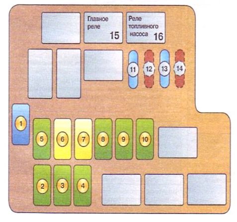
Version No. 4
The fourth version of the Mazda 626 / Capella gf underhood fuse box design.
| Diagram | ||
|---|---|---|
|
||
| No. | Description | Amps |
| 1 | Main power supply circuit | 100 |
| 2 | Headlights | 40 |
| 3 | Electric rearview mirrors, rear window heater | 40 |
| 4 | Fuel injection system | 30 |
| 5 | Radio, power sunroof, turn indicators, gauges, engine ECU, power windows, ignition system, front wipers | 40 |
| 6 | Rear light bulbs, fog light bulbs, brake lights, interior lamps, hazard warning lamps, electric door locks, power seat adjustment system | 60 |
| 7 | Anti-lock brake system (ABS) | 60 |
| 8 | Cooling Fan | 40 |
| 9 | Heater, air conditioner | 40 |
| 10 | Air conditioner | 40 |
| 11 | Tail lamps, parking lamps, instrument cluster, glove compartment lamp | 15 |
| 12 | — | — |
| 13 | Fog lamps | 15 |
| 14 | ~ | — |
| 15 | Main relay | |
| 16 | Fuel pump relay | |
Separate relay modules
The relay modules are located both in and outside the distribution boxes, on the left and right side (cooling fans, heating, ABS brake, glow plugs, etc.).
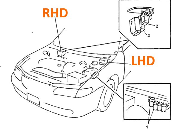
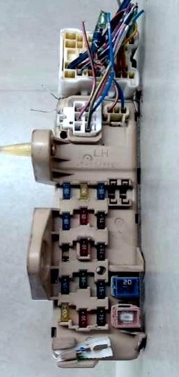
In the passenger compartment
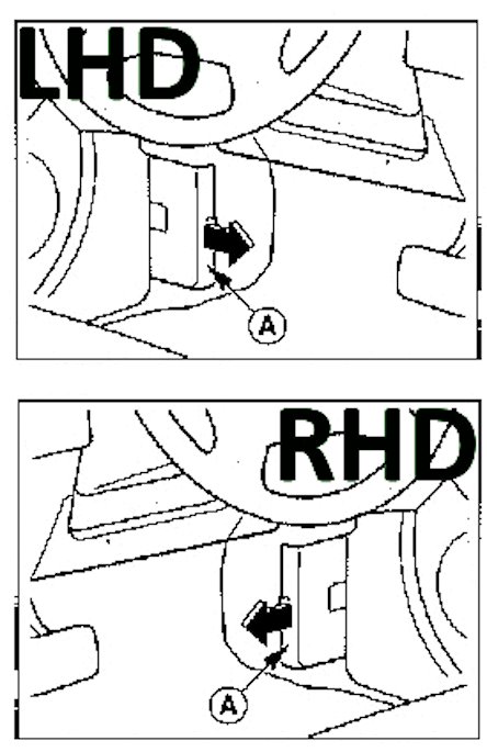
The unit is behind the plastic cover on the rack, near the driver's door.
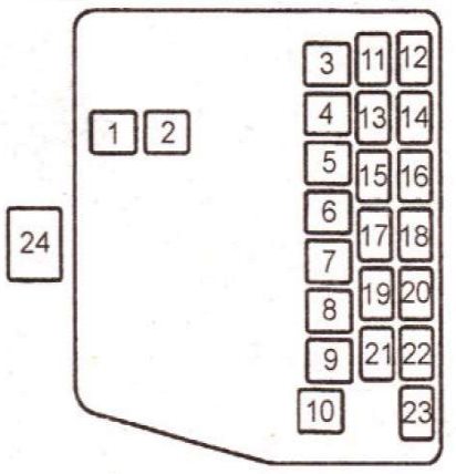
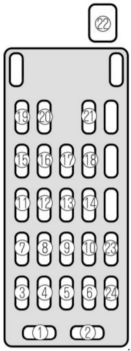
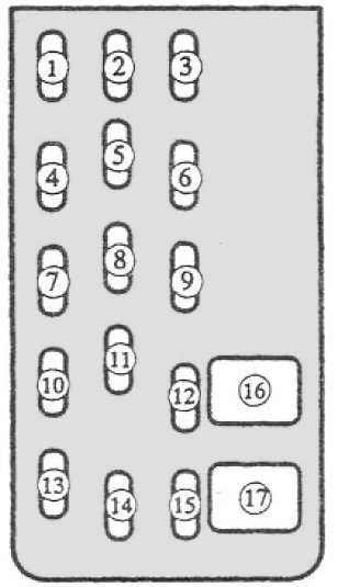
Version No. 1
The first version of the Mazda 626 gf passenger compartment fuse box design.
| Diagram | ||
|---|---|---|
|
||
| No. | Description | Amps |
| 1 | audio system | 15 |
| 2 | interior lighting, trunk lighting | 15 |
| 3 | Sunroof | 15 |
| 4 | sensors and reversing lights, instrument panel | 10 |
| 5 | door lock drive, central locking | 30 |
| 6 | hazard lights | 15 |
| 7 | airbags, ABS anti-lock system | 10 |
| 8 | Spare | |
| 9 | A/C - air conditioning | 10 |
| 10 | Spare | |
| 11 | TURN - direction indicators | 10 |
| 12 | WIPER - wipers and glass cleaners | 20 |
| 13 | P.WIND - power windows | 30 |
| 14 | Not used | |
| 15 | RADIO - audio system, side mirrors | 15 |
| 16 | ENGINE - engine management system | 10 |
| 17 | ILLUMI - license plate lights, parking lights, dashboard lights | 10 |
| 18 | STOP - brake lights, horn, cruise control | 15 |
| 19 | Mazda 626 / Capella Cigarette Lighter, Clock, Radio, Side Mirrors Fuse | 15 |
| 20 | Not used | - |
| 21 | - | |
| 22 | P.SEAT - power seats | 30 |
| 23 | M.DEF - heated mirrors | 15 |
| 24 | P.POINT - power supply for optional equipment | 15 |
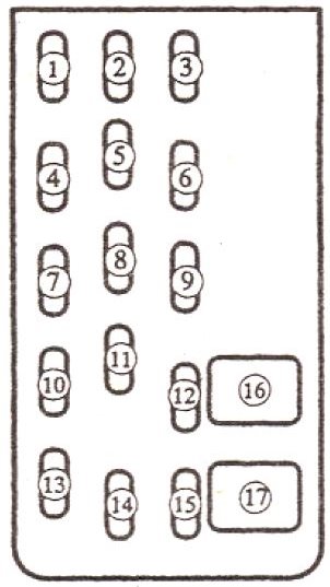
Version No. 2
General view.
| Diagram | ||
|---|---|---|
|
||
| No. | Decoding | Amps |
| 1 | Optional equipment*, fuse for various circuits, mazda 626 cigarette lighter fuse | 15 |
| 2 | Windshield wipers and washers | 20 |
| 3 | Air conditioning*, sunroof", fuse for various circuits | 15 |
| 4 | Radio, fuse for various circuits | 15 |
| 5 | Rear window wiper / tailgate window", fuse for various circuits | 10 |
| 6 | The engine control unit | 7.5 |
| 7 | Empty | - |
| 8 | Interior lighting, trunk/luggage compartment lighting | 10 |
| 9 | Heated mirrors, fuse for various circuits | 7.5 |
| 10 | Empty | - |
| 11 | Central locking*, fuse for various circuits | 30 |
| 12 | Fuse for various circuits - TAIL | 15 |
| 13 | Empty | - |
| 14 | Engine management system, ABS brake system* | 10 |
| 15 | Instrument cluster, turn indicators, reversing lights | 10 |
| 16 | Power windows | 20 |
| 17 | 30 | |
| Note : * - some models. | ||
Version No. 3
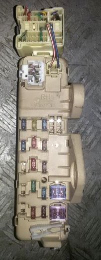
The unit itself has exactly the same look as the second version, but the purpose of the fuses in it is different.
| Diagram | ||
|---|---|---|
|
||
| No. | Decoding | Amps |
| 1 | Heated seats | 15 |
| 2 | Headlamp cleaner | 20 |
| 3 | Audio system, center console, clock, radio | 15 / 20 |
| 4 | Air conditioning, sunroof | 15 |
| 5 | R/WIPER — Rear window wiper | 10 |
| 6 | ENG - Engine management | 10 |
| 7 | Not used | - |
| 8 | ROOM - Interior lighting | 10 |
| 9 | MIRR/DEF — Heated mirrors | 10 |
| 10 | Heated seats | 15 |
| 11 | DOOR LOCK - Central locking | 30 |
| 12 | TAIL - Headlights, tail lights, parking lights | 15 / 20 |
| 13 | Windshield wiper / washer | 20 |
| 14 | ENGINE - Engine management system, ABS system | 10 |
| 15 | Instrument cluster, turn indicators, reversing lights | 15 |
| 16 | Not used | - |
| 17 | Power windows | 30 |
In this variation, there is no dedicated cigarette lighter fuse, but it is powered from #3. If the cigarette lighter fuse is defective and the fuse itself is working, check the wire behind it. |
||
