
626 / Cronos is the export market designation for the Mazda Capella, produced for international markets from 1978 to 2002 across five generations. This guide provides detailed fuse box and relay panel diagrams for fourth-generation (GE platform) Mazda 626 / Cronos models produced from 1991 through 1997.

Below are the locations and photographic diagrams for all power distribution blocks. The circuits for the “Cigarette Lighter” and “Fuel Pump” are highlighted in bold.
Engine Compartment Fuse Box
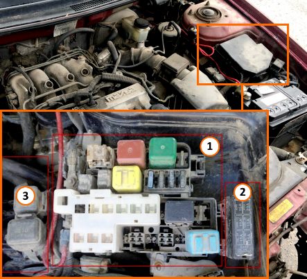
Up to three distinct blocks may be located in the engine compartment: 1 – Main Fuse Box, 2 – Auxiliary Fuse Box, and 3 – Relay Box.
Main Fuse & Relay Box
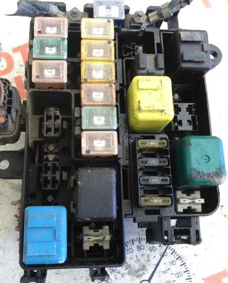
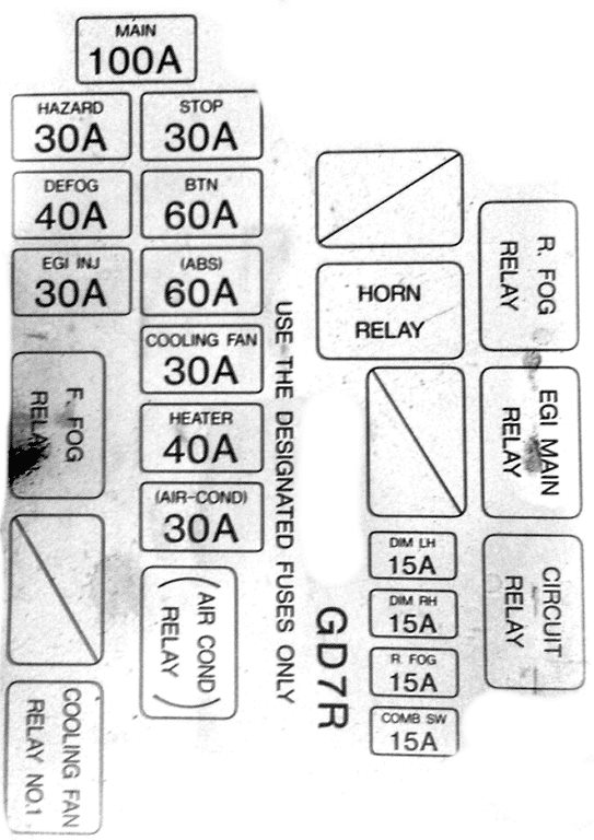
Representative sample configuration shown below.
| Diagram | ||
|---|---|---|
|
||
| Code | Circuit Protected | Rating (A) |
| MAIN | Main fuse | 100 |
| HAZARD | Hazard warning lights | 30 |
| DEFOG | Rear window defogger | 40 |
| ENG INJ | Fuel injection system | 30 |
| STOP | Brake lights | 30 |
| BTN | Power door locks, power seats | 60 |
| ABS | Anti-lock Braking System (ABS) | 60 |
| Cooling fan relay 1 |
Cooling fan | 30 |
| HEATER | Blower motor, HVAC system | 40 |
| AIR COND | Air conditioning system | 30 |
| DIM LH | Low beam (left headlight) | 15 |
| DIM RH | Low beam (right headlight) | 15 |
| R.FOG | Rear fog lights | 15 |
| COMB SW | Combination switch (turn signals, wipers) | 15 |
| R.FOG RELAY |
Rear fog lamp relay | |
| EGI MAIN RELAY |
Engine control (EGI) main relay | |
| CIRCUIT RELAY |
Fuel pump relay | |
| FOG RELAY |
Front fog lamp relay | |
| Cooling fan relay 1 |
Cooling fan relay 1 | |
| AIR COND RELAY |
Air conditioning relay | |
| HORN RELAY |
Horn relay | |
Auxiliary Fuse Box
Circuit assignments:

|
||
| Code | Circuit Protected | Rating (A) |
| MAIN LH | Headlight (left) | 15 |
| MAIN RH | Headlight (right) | 15 |
| HORN | Horn | 15 |
| FOG | Front fog lights | 20 |
| TAIL LH | Parking / Tail lights (left) | 15 |
| TAIL RH | Parking / Tail lights (right) | 15 |
Auxiliary Relay Modules

Depending on market specification, standalone relay modules may be located near the main fuse box or on the right side of the engine compartment (housing relays for cooling fans, HVAC, fog lights, etc.).
Passenger Compartment Fuse Box
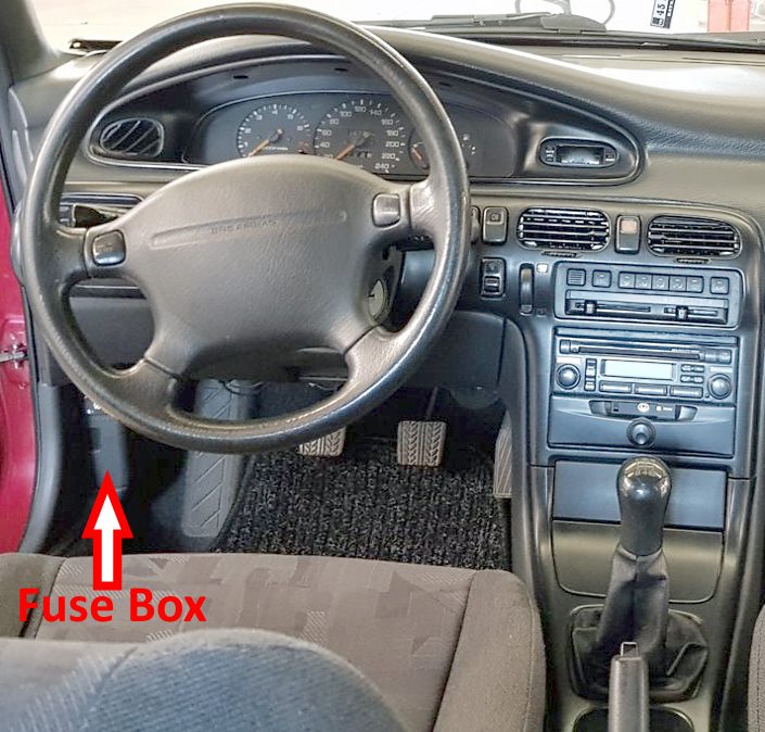
Located under the driver's side dashboard behind the plastic kick panel cover.

General view of the interior fuse panel layout.
| Diagram | ||
|---|---|---|

|
||
| No. | Circuit Protected | Rating (A) |
| 1 | STOP – Brake lights, horn, cruise control | 20 |
| 2 | ROOM – Interior dome light, trunk light, key warning switch | 15 |
| 3 | DOOR LOCK – Power door lock actuators (central locking) | 30 |
| 4 | RADIO – Audio system, cigarette lighter, power mirrors | 15 |
| 5 | SUNROOF – Power sunroof | 15 |
| 6 | TURN – Direction indicators (turn signals) | 15 |
| 7 | POWER SEAT – Power seats | 30 |
| 8 | METER – Instrument cluster, reverse (backup) lights | 15 |
| 9 | HAZARD – Hazard warning lights | 15 |
| 10 | ENGINE – Engine control unit (ECU) | 15 |
| 11 | POWER WINDOW – Power windows | 30 |
| 12 | HEAD CLEANER – Headlight washers | 20 |
| 13 | WIPER – Windshield wipers and washer fluid pump | 20 |
| 14 | REAR WIPER – Rear wiper and washer pump | 20 |
| 15 | Not used | 15 |
