
The third-generation Mazda6 debuted at the 2012 Moscow Motor Show. The model received its first facelift in 2015, followed by a second update in 2018, which refreshed both exterior styling and interior design. This guide details the fuse box diagrams, relay assignments, and circuit layouts for the Mazda6 (3rd generation; chassis code GJ) manufactured from 2012 through 2020.

Below are the locations, diagrams, and photos of the power distribution boxes. Fuses for the “Cigarette Lighter” and “Fuel Pump” circuits are highlighted in bold.
Engine Compartment Fuse Box
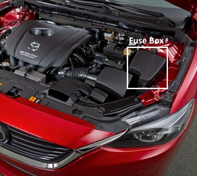
The fuse box is located in the engine bay next to the battery. Remove the protective cover to gain access.

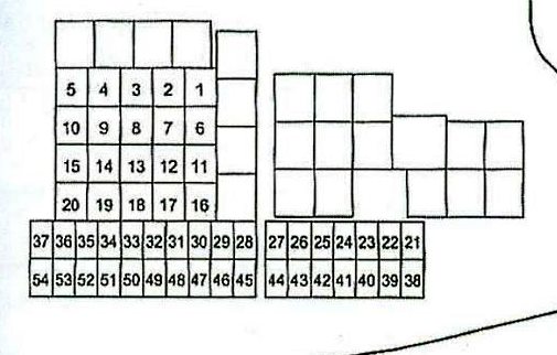
General layout.
| Diagram | ||
|---|---|---|
|
||
| No. | Rating (A) | Circuit Protected / Function |
| 1 | 30 | Engine cooling fan (if equipped) |
| 2 | 30 | Multi-circuit protection (IG2 supply) |
| 3 | 30 | Engine control system – Fuel injectors (if equipped) |
| 4 | 40 | Engine cooling fan (if equipped) |
| 5 | 30 | Power windows (if equipped) |
| 6 | - | Not used |
| 7 | 40 | Engine cooling fan (if equipped) |
| 8 | 20 | Engine control system – Electric Variable Valve Timing (e-VVT) (if equipped) |
| 9 | 40 | Heated rear window (defogger) |
| 10 | 40 | Multi-circuit protection – DC-DC converter (if equipped) |
| 11 | 30 | Engine cooling fan (if equipped) |
| 12 | - | Not used |
| 13 | - | |
| 14 | - | |
| 15 | 40 | Engine control system (ENG MAIN) |
| 16 | 50 | Anti-lock Braking System (ABS) / Dynamic Stability Control (DSC) |
| 17 | 50 | Multi-circuit power supply – Cabin main (+B) |
| 18 | 20 | Windshield wiper and washer |
| 19 | 40 | Air conditioning (A/C) system |
| 20 | 30 | Multi-circuit protection (if equipped) |
| 21 | 7.5 | Engine control system |
| 22 | 15 | Multi-circuit protection |
| 23 | 15 | Headlight (LH)*1 / Low-beam headlight (LH)*2 |
| 24 | 15 | Low-beam headlight (RH)*2 |
| 25 | 15 | Engine control system (ENGINE 3) |
| 26 | 15 | Engine control system (ENGINE 2) |
| 27 | 15 | Engine control system (ENGINE 1) |
| 28 | 15 | Transmission Control Module (TCM) (if equipped), ignition switch |
| 29 | 20 | Headlight washers (if equipped) |
| 30 | 7.5 | Air conditioning (A/C) controls |
| 31 | 15 | Transmission Control Module (TCM) (if equipped) |
| 32 | 10 | Brake lights, rear fog light (if equipped) |
| 33 | 15 | Rear window wiper (if equipped) |
| 34 | 20 | High-beam headlights |
| 35 | 15 | Headlight (RH)*1 |
| 36 | 15 | Front fog lights (if equipped) |
| 37 | 7.5 | Engine control system (ENG +B) |
| 38 | 7.5 | Audio system |
| 39 | 5 | Engine control system – Glow plug signal (if equipped) |
| 40 | 7.5 | Instrument cluster (if equipped) |
| 41 | 10 | Instrument cluster |
| 42 | 7.5 | Supplemental Restraint System (SRS1 / Airbags) |
| 43 | 25 | Bose premium audio system (if equipped) |
| 44 | 15 | Audio system |
| 45 | 30 | Anti-lock Braking System (ABS) / Dynamic Stability Control (DSC) |
| 46 | 15 | Fuel system – fuel pump (if equipped) |
| 47 | 25 | Fuel heater (FUEL WARM) (if equipped) |
| 48 | - | Tail lights |
| 49 | - | Not used |
| 50 | 50 | Turn signals, parking lights, tail lights, license plate lights |
| 51 | - | Daytime running lights (DRL) |
| 52 | 15 | Auxiliary power outlets (R.OUTLET2) |
| 53 | 15 | Horn |
| 54 | 15 | Interior lighting |
| Note: *1. Headlights with High-Intensity Discharge (Xenon) lamps; *2. Headlights with halogen lamps. | ||

Relay diagram and component designations:
- FUEL PUMP RELAY – Fuel pump
- OUTLET RELAY – Auxiliary power outlets
- HEADLIGHT LO RELAY – Low-beam headlights
- IG1 RELAY – Ignition system
- FRONT FOG LIGHTS RELAY – Front fog lights
- COOLING FAN RELAY NO.2 – Engine cooling fan No. 2
- MAIN RELAY – Main system relay
- COOLING FAN RELAY NO. 3 – Engine cooling fan No. 3
- DRL RELAY – Daytime running lights
- HORN RELAY – Horn
- COOLING FAN ACC RELAY – Engine cooling fan No. 1
- TNS RELAY (TAIL) – Parking lights / tail lights
- A/C RELAY – Air conditioning compressor clutch
- FUEL INJECTOR RELAY – Fuel injectors
- ELECTRIC AT OR OIL PUMP RELAY – Electric automatic transmission / transmission oil pump
- HEADLIGHT HI RELAY – High-beam headlights
- STARTER RELAY – Starter motor
- BLOWER RELAY – Blower motor (HVAC)
- ELECTRIC VARIABLE VALVE TIMING RELAY – Electric Variable Valve Timing (e-VVT)
- REAR WINDOW DEFROSTER RELAY – Heated rear window
Passenger Compartment Fuse Box

Located on the kick panel near the driver's left footwell. Remove the plastic trim cover to gain access.

General view of the interior fuse box (Mazda6 GJ).
| Diagram | ||
|---|---|---|

|
||
| No. | Circuit Protected / Description | Rating (A) |
| 1 | P.SEAT D – Power driver seat adjustment (if equipped) | 30 |
| 2 | P.WINDOW 3 – Power windows | 30 |
| 3 | R.OUTLET3 – Rear auxiliary power outlets | 15 |
| 4 | P.WINDOW 2 – Power windows | 25 |
| 5 | SRS2 / ESCL – Steering column lock / SRS airbags | 15 |
| 6 | D.LOCK – Power door locks | 25 |
| 7 | SEAT WARM – Heated front seats (if equipped) | 20 |
| 8 | SUNROOF – Moonroof / sunroof (if equipped) | 10 |
| 9 | F.OUTLET – Front accessory power socket / cigarette lighter | 15 |
| 10 | MIRROR – Power exterior mirrors | 7.5 |
| 11 | R.OUTLET1 – Rear power outlets (if equipped) | 15 |
| 12 | Not used | - |
| 13 | Not used | - |
| 14 | Not used | - |
| 15 | Not used | - |
| 16 | Not used | - |
| 17 | M.DEF – Heated exterior mirrors | 7.5 |
| 18 | R.SEAT W – Heated rear seats (if equipped) | 20 |
| 19 | Not used | - |
| 20 | AT IND – Automatic transmission shift indicator | 7.5 |
| 21 | P.SEAT P – Power passenger seat adjustment | 30 |

43 25A BOSE - Cars equipped with Bose audio system
I need to replace this one. Do you know the actual name of the 25a fuse. Looking for them on Amazon but I don't see one that looks like the one in my car. All of the ones on Amazon have prongs that stick out. The ones in the car are really short and don't have those.