The premiere of the second generation Mazda 6 took place in 2007 at the Frankfurt Motor Show. In 2010, a restyling of the model took place. In this article, we will take a detailed look at the fuse box diagrams for the Mazda 6 (codename GH) 2007, 2008, 2009, 2010, 2011, 2012 years of manufacture.

Here you will find the locations and photos of distribution boxes. The fuses responsible for the “Cigarette lighter” and “Fuel Pump” are highlighted in bold.
In the engine compartment
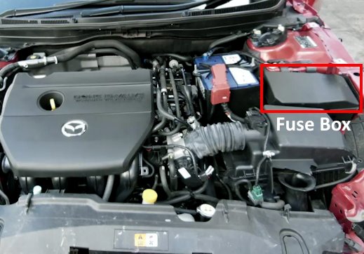
The distribution box is located on the left side of the underhood, near the battery.
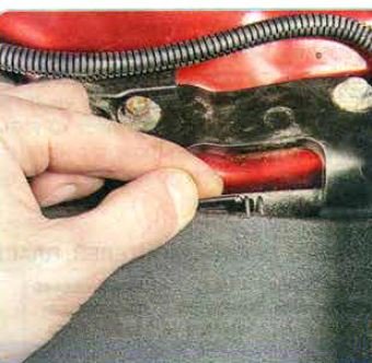
1) To gain access to the distribution box located in the engine compartment, press the cover latch...
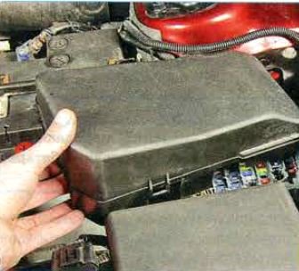
2) ...and remove the cover.
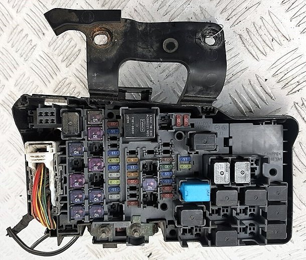
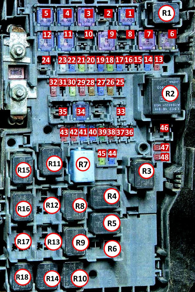
General view.
| Diagram | ||
|---|---|---|
|
||
| No. | Amps | Description |
| Relay | ||
| R1 | A/C compressor relay | |
| R2 | Main relay | |
| R3 | Dipped beam relay | |
| R4 | Starter relay | |
| R5 | Horn relay | |
| R6 | Tail lights | |
| R7 | Fuel pump relay | |
| R8 | Power outlets relay | |
| R9 | Engine cooling fan low speed switch | |
| R10 | ||
| R11 | High beam relay | |
| R12 | Engine cooling fan high speed relay | |
| R13 | ||
| R14 | Rear window defroster relay | |
| R15 | Starter relay | |
| R16 | Front fog lamp relay | |
| R17 | Not used | |
| R18 | Heater relay | |
| Fuses | ||
| 1 | 40 | Heater |
| 2 | 40 | Spare |
| 3 | 30 | Electric windows |
| 4 | 40 | Engine starting system |
| 5 | 40 | Electrical circuit protection |
| 6 | 60 | Anti-lock braking system ABS |
| 7 | 30 | Electric fan of the engine cooling system |
| 8 | 20 | AUX HEATER (heater) |
| 9 | 30 | Electric fan of the engine cooling system |
| 10 | 50 | PRECRASH |
| 11 | 40 | Rear window defroster |
| 12 | 40 | Power seat adjustment |
| 13 | 10 | Air conditioning system |
| 14 | 15 | Power outlet |
| 15 | - | DIECER |
| 16 | - | No used |
| 17 | 15 | Sunroof |
| 18 | 20 | Seat heating |
| 19 | 15 | Interior equipment control unit |
| 20 | 25 | Audio system |
| 21 | 20 | headlight washer |
| 22 | 15 | Fog lights |
| 23 | 25 | Electric door lock actuator |
| 24 | - | Not used |
| 25 | - | Not used |
| 26 | 5 | Brake lights |
| 27 | 15 | Horn |
| 28 | 5 | Engine management system |
| 29 | 10 | Turn indicators and emergency signaling |
| 30 | - | Not used |
| 31 | 10 | Electronic steering lock system |
| 32 | 10 | Engine management system |
| 33 | - | Not used |
| 34 | 40 | Protection of electrical circuits |
| 35 | - | Not used |
| 36 | - | GLOWSIG |
| 37 | - | Not used |
| 38 | 7.5 | Electric mirror heating |
| 39 | 30 | ABS anti-lock braking system and stabilization system |
| 40 | 15 | Right low beam headlights |
| 41 | 15 | Left dipped beam bulb |
| 42 | 10 | Right high beam bulb |
| 43 | 10 | Right dipped beam bulb |
| 44 | 15 | Injectors |
| 45 | 20 | Fuel module (fuel pump fuse) |
| 46 | - | GLOW (glow plugs) |
| 47 | 10 | Engine management system |
| 48 | 10 | Injectors |
In the passenger compartment
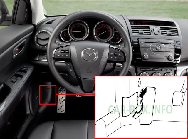
The distribution box is located on the driver's side near the door, behind the plastic cover.
1) To access the distribution box located in the passenger compartment, release the lock and slide the cover sideways....
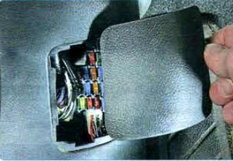
2) ...remove it from the end of the lower trim of the front door pillar, overcoming the elastic resistance of the retainers.
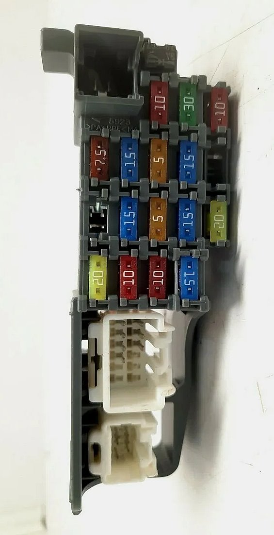
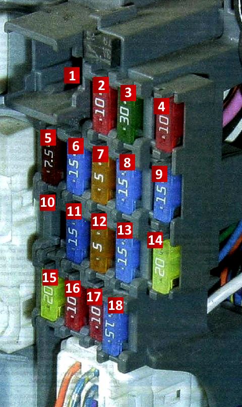
General view of the Mazda 6 gh interior fuse box.
| Diagram | ||
|---|---|---|
|
||
| No. | Amps | Decoding |
| 1 | 30 | Power windows |
| 2 | 10 | Adaptive lighting system |
| 3 | 30 | Central door locking |
| 4 | - | Not used |
| 5 | 7.5 | Dashboard lighting |
| 6 | 15 | Mazda 6 cigarette lighter fuse |
| 7 | 5 | Electrically operated side mirrors |
| 8 | 15 | Power outlets |
| 9 | - | Not used |
| 10 | - | Not used |
| 11 | 15 | Engine management system |
| 12 | 5 | Safety system |
| 13 | 15 | Instrument panel |
| 14 | - | Not used |
| 15 | 20 | Windshield wiper and washer |
| 16 | 10 | air conditioner compressor |
| 17 | 10 | Rear door wiper and windshield washer |
| 18 | 15 | Interior lamps |
