Mercedes-Benz B-Class is a series of compact cars by the German automaker. It was first introduced in 2005 at the Geneva Motor Show, and was preceded by the Vision B concept car. It is produced in Rastatt. In this article, we will take a detailed look at the fuse box diagrams for the Mercedes W245 B-Class (1st gen; B160, B170, B180, B200) 2005, 2006, 2007, 2008, 2009, 2010, 2011, 2012 years of manufacture

Here you will find the locations and photos of distribution boxes. The fuses responsible for the “Cigarette lighter” and “Fuel Pump” are highlighted in bold.
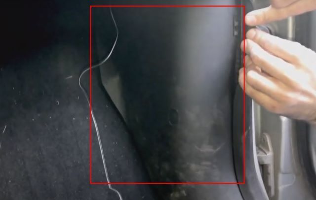
In the passenger compartment
There are two distribution boxes here that are responsible for protecting the electrical circuits.
Fuse box
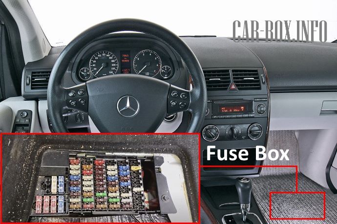
It is located in the front passenger footwell. It can be accessed by removing the floor pan.

General view of the Mercedes B-Class W245 cabin fuse box.
| Diagram | ||
|---|---|---|
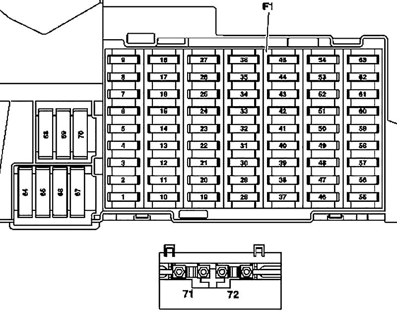
|
||
| No. | A | Description |
| 1 | 10 | 2005-2008: Brake light switch |
| 5 | 2008-2012 and 2005-2008 with code U58: Brake light switch | |
| 2 | 25 | Rear window heating |
| 3 | 7.5 | Instrument cluster |
| EZS module | ||
| 4 | 15 | EZS module |
| Electronic steering lock module | ||
| 5 | 7.5 | HAU module |
| KLA module (automatic air conditioning) | ||
| 6 | 15 | Horn (beep) |
| 7 | 25 | Fuel module (fuel pump fuse) with fuel level sensor |
| 8 | 25 | Overhead control panel |
| 9 | 40 | ESP and BAS control module |
| 10 | 40 | Fan motor |
| 11 | 30 | Motor 266: Relay circuit terminal 87, motor |
| 40 | Motor 640: Relay circuit terminal 87, motor | |
| 12 | 5 | Steering column electronics |
| Multifunction steering wheel | ||
| 13 | 25 | Front Left Door Control Module |
| 14 | 25 | Front Right Door Control Module |
| 15 | 25 | ESP and BAS control module |
| 16 | 10 | Diagnostic connector |
| PTS control module (parktronic, 2005-2008) | ||
| 17 | 5 | Outdoor lighting rotary switch |
| 18 | 7.5 | Gearbox 711, 716: Reverse light switch |
| 19 | 5 | Micromechanical angular velocity sensor AY |
| 20 | 7.5 | Passive safety system control module |
| 21 | 30 | Starter |
| 22 | 7.5 | Instrument cluster |
| 23 | 20 | Motor 640 (from 1.9.2008): Fuel filter condensate sensor with heating element |
| 7.5 | 2005-2008: Heated washer nozzles | |
| 24 | 7.5 | Electric Power Steering (ES) Control Module |
| 25 | 7.5 | Brake light switch |
| ESP and BAS control module | ||
| 26 | 7.5 | gearbox 722: Control unit of the electronic selector lever module |
| 27 | 10 | gearbox 722: CVT (continuously variable automatic transmission) electrical control module |
| 28 | 5 | Outdoor lighting rotary switch |
| 29 | 30 | SAM control module |
| 30 | 25 | Relay of the electric circuit of terminal 87F |
| 31 | 5 | Outdoor lighting rotary switch |
| Central interface module (vehicles up to 30.11.05) | ||
| 32 | 7.5 | Engine 266.920: Module ME |
| 33 | 15 | Audio system |
| Audio module and navigation box | ||
| Control panel COMAND | ||
| 34 | 25 | Rear left door module |
| 35 | 25 | Rear right door module |
| 36 | 10 | 2008-2012 : PTS module (parking sensors) |
| 7.5 | 2005-2008: Trailer module | |
| Cell phone circuit connector | ||
| 37 | 7.5 | Passive safety system control module |
| Passenger/child seat detection sensor on the front passenger seat | ||
| Front passenger seat occupancy detection system | ||
| 38 | 25 | Front cigarette lighter fuse Mercedes 245 |
| 39 | 25 | Wiper motor |
| 40 | 25 | Sectional roof: Overhead control panel (sunroof motor) |
| 7.5 | Overhead control panel | |
| 41 | 15 | Tailgate wiper motor |
| 42 | 7.5 | Duffel box lighting with microswitch |
| Lighting of the cosmetic mirror left and right | ||
| Pedal pedal control sensor (driving school package) | ||
| Footwell light switch (driving school package) | ||
| Pluggable connection VICS + ETC power supply (Japan) | ||
| Emergency call system module (USA) | ||
| 43 | 7.5 | Motor 266: electrical circuit lug of terminal 87M1e |
| 15 | Motor 640: electrical circuit lug of terminal 87M1e | |
| Dual-fuel gasoline engine: electrical circuit lug of terminal 87M1e | ||
| 44 | 15 | Motor 266: electrical circuit lug of terminal 87M2e |
| 20 | Motor 640: electrical circuit lug of terminal 87M2e | |
| 45 | 25 | Engine 640: CDI System Module |
| 46 | 25 | Woofer (Japan, 2008-2012) |
| 40 | Speaker amplifier (2008-2012) | |
| 7.5 | UHI Module (Universal Mobile Phone Interface) (2005-2008) | |
| GSM 1800 network compensator (2005-2008) | ||
| Telephone control module (Japan, 2005-2008) | ||
| 47 | 7.5 | Cell phone circuit connector |
| UHI Control Module (Universal Mobile Phone Interface) | ||
| Voice control system control module (2005-2008) | ||
| Telephone control module (Japan, 2005-2008) | ||
| 48 | 7.5 | EDW control unit / towing protection / interior protection systems |
| Alarm siren | ||
| 49 | 25 | left front seat cushion heating element (2005-2008) |
| Front Left Seat Backrest Heating Element (2005-2008) | ||
| Front Right Seat Cushion Heating Element (2005-2008) | ||
| Front Right Seat Backrest Heating Element (2005-2008) | ||
| 50 | 7.5 | Multimedia Interface Control Module (2008-2012) |
| Digital TV Tuner (2008-2012) | ||
| Digital sound broadcasting system module (2008-2012) | ||
| CD changer (2005-2008) | ||
| VICS + ETC power supply plug-in connection (Japan, 2005-2008) | ||
| 30 | Service vehicles: Roof beam | |
| Cable lug for electrical circuit terminal 30 | ||
| 51 | 10 | Passenger Weight System (WSS) Control Module (Canada) |
| Control panel for special signaling system (service vehicles) | ||
| 52 | 7.5 | Emergency call system control module (vehicles up to 31.5.06) |
| 5 | VICS + ETC power supply connector (Japan, vehicles up to 31.5.06) | |
| 53 | 30 | Cabin 12V socket |
| Rear cigarette lighter fuse w245 | ||
| 54 | 15 | Service vehicles: 2-pin 12V socket |
| 25 | Speaker amplifier (2005-2008) | |
| Woofer (2005-2008) | ||
| 55 | 10 | Front left headlamp |
| 56 | 10 | Front right headlamp |
| 57 | 15 | AHV trailer coupling, 13-pin (2008-2012) |
| 20 | audio interface (Japan. 2005-2008) | |
| 7.5 | emergency call system | |
| SDAR | ||
| 58 | 25 | Trailer control unit |
| 59 | 20 | AHV trailer coupling, 13-pin |
| Trailer control unit (vehicles up to 31.5.2005) | ||
| 60 | 20 | Driver's seat contact strip |
| 61 | 20 | Front passenger seat contact strip |
| 62 | 40 | 2008-2012: Relay circuit terminal 15 (2) (optional equipment: xenon headlights, cell phone) |
| 25 | 2005-2008: Relay circuit terminal 15 (2) (optional equipment: xenon headlights, cell phone) | |
| 63 | 7.5 | SDAR (Canada) |
| 25 | Roof beam (company cars) | |
| 64 | 40 | Engine 266: Air Pump Relay |
| 80 | Engine 640: glow plug timer | |
| 65 | 80 | Electric power steering (ES) control unit |
| 66 | 60 | SAM control unit |
| 67 | 50 | Circuit relay terminal 15R (2) (optional equipment) |
| 68 | 50 | Standard equipment (2008-2012): Engine and A/C suction fan with integrated regulator (2005-2008: (valid for 266.920 and 266.940 engine with gearbox 722)) |
| 60 | Special equipment (2008-2012): 2005-2008: (valid for engines 640.940, 640.941, 266.960, 266.980 and engines 266.920, 266.940 with code (550): Trailer coupling)) | |
| 69 | 50 | terminal 15R circuits (1) |
| 70 | 60 | terminal 15 circuits (1) |
| 71 | 150 | Engine 640: PTC Auxiliary Heater |
| 72 | 60 | 2005-2008: electric circuit lug terminal 30 |
| Service vehicles: Fuse 7 (F7f7) and 10 (F7f10) | ||
| Cab: Multifunctional Unit (MSS) | ||
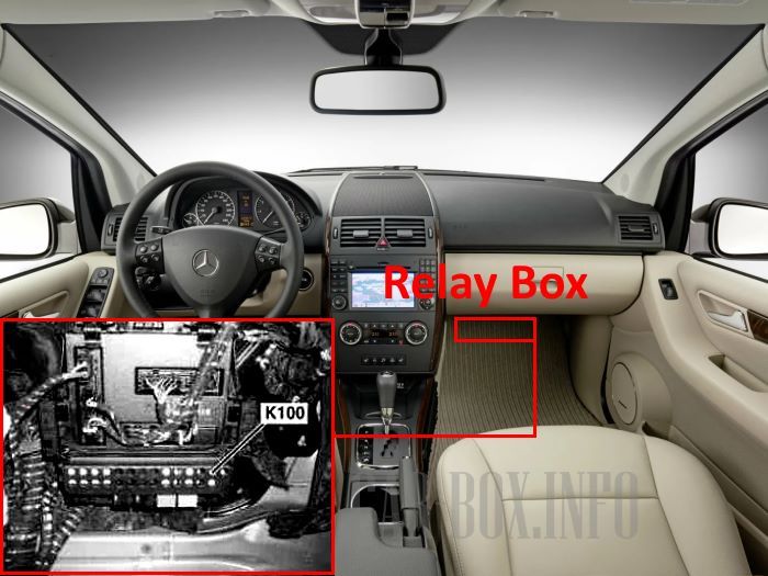
Relay box
The optional K100 wiring block with relay modules is located under the instrument panel.
For access:
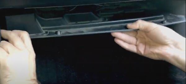
1. Remove the trim under the glove compartment.
2. Remove the panel near the door.
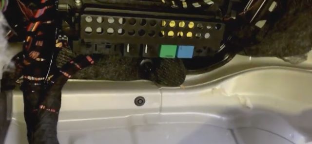
3. Move the floor trim aside.
| Diagram | ||
|---|---|---|
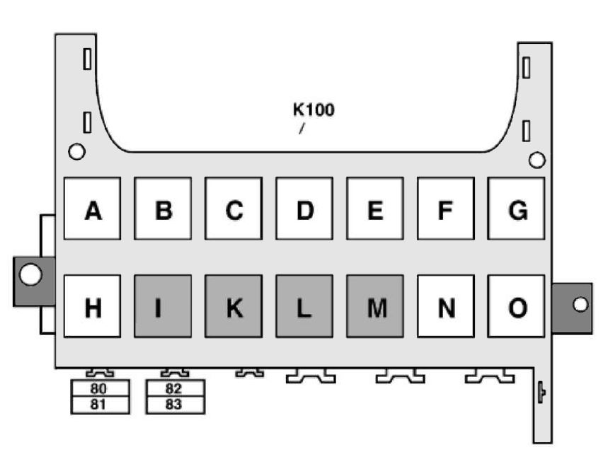
|
||
| No. | Description | |
| A | Relay, circuit 15R (2) (SA) | |
| B | Circuit 15R relay (1) | |
| C | Horn (beep) relay | |
| D | Rear window heating | |
| E | 1/2 wiper speed | |
| F | Turning on / off the wiper | |
| G | Circuit 15 (1) | |
| H | Reserve | |
| I | Motor 266: air pump | |
| K | Fuel pump relay (gasoline) | |
| L | Engine circuit 87 relay | |
| M | Starter | |
| N | Relay, circuit 87F | |
| O | Relay, circuit 15 (2) (SA: xenon, cell phone) | |
| No. | Appointment | A |
| 80- 81 |
Special equipment | 30 |
All electrical equipment
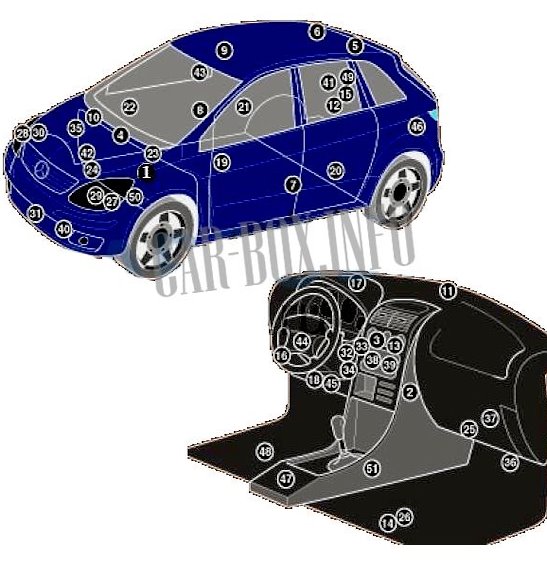
General layout of the electrical system in the vehicle.
1. ABS module;
2. Heater/air conditioner fan motor resistor;
3. Air conditioning/heater control module-behind the air conditioning/heater control panel;
4. Air conditioning/heating humidity sensor on the intake system resonator;
5, 6. Antenna on the roof panel;
7. impact sensor, driver's side;
8. Impact sensor, passenger side;
9. Anti-theft system control unit;
10. Anti-theft system siren on the intake system resonator;
11. Sun sensor;
12. Audio amplifier - behind the right rear side trim panel;
13. Auxiliary heater control module-in the air conditioner control panel;
14. Battery - footwell;
15. CAN data bus, gateway control unit, audio system - behind the right rear side trim panel;
16. CAN data bus, gateway control unit - behind the instrument panel;
17. Compass control unit behind the instrument cluster;
18. Diagnostic connector (DLC);
19. Driver's door electrical control unit - in the door;
20. Electrical control unit for the left rear door - in the door;
21. Electrical control unit for the right rear door - in the door;
22. Passenger door electrical control unit-in the door;
23. Engine-Diesel ECU;
24. ECU - gasoline;
25. Relay box, instrument panel;
26. Fuse box, footwell;
27. Xenon headlight control unit, left. - under the left headlight;
28. Xenon headlight control unit, right. - under right headlamp;
29. Headlamp corrector motor, left;
30. Headlight correction motor, right;
31. Horn (beep);
32. Ignition switch control module;
33. Immobilizer ECU - in ignition switch control module;
34. Immobilizer ring antenna - in ignition switch control unit;
35. ECU for the gas filling system;
36. Multifunction control unit - functions: Brake fluid low level sensor, central locking, coolant level sensor, exterior lamps, interior lamps, hazard warning light, turn signal indicators, rear window heater, horn, reverse light switch, tailgate opening actuator, windshield wiper/washer, rear window wiper/washer;
37. Multimedia control unit;
38. Multifunction switch control unit;
39. Navigation system control unit - in the audio system unit;
40. Outside temperature sensor - behind the bumper;
41. Parktronic control module - behind the right rear side trim panel;
42. Power steering control module - on the steering rack;
43. Rain sensor - top center of the windshield;
44. Steering column electrical control unit - under the steering wheel;
45. Steering column lock control unit - on the steering column;
46. Subwoofer - behind the left rear side trim panel;
47. SRS ECU - under the center console;
48. Phone interface control unit - under the seat;
49. Trailer electrical control unit - in the rear rear side trim panel;
50. Transmission ECU - in the transmission;
51. Gearshift control unit - selector lever.

Very helpful