The second generation of Mercedes-Benz A-Class was introduced in 2004. The car body was assembled from high-strength steel alloys with special glue joints, inheriting the "sandwich" architecture from its predecessor. In 2008, the car underwent a facelift. In this article, we will take a detailed look at the fuse box diagrams for the Mercedes A-class W169 (2nd gen; A150, A160, A170) 2004, 2005, 2006, 2007, 2008, 2009, 2010, 2011, 2012 years of manufacture.

Here you will find the locations and photos of distribution boxes. The fuses responsible for the “Cigarette lighter” and “Fuel Pump” are highlighted in bold.
In the passenger compartment
There are two distribution boxes here that are responsible for protecting the electrical circuits.
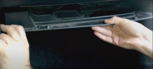
Fuse box
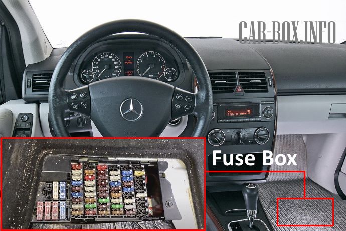
It is located in the front passenger footwell. It can be accessed by removing the floor lining.
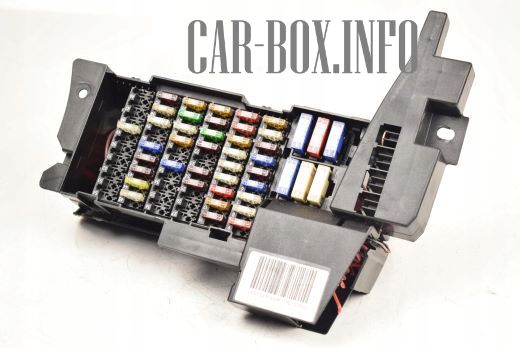
General view of the Mercedes A-Class W169 interior fuse box.
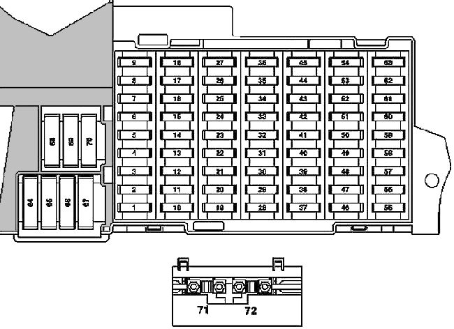
| Diagram | ||
|---|---|---|
|
||
| No. | A | Description |
| 1 | 10 | Before 2008 restyling: Brake signal switch |
| 5 | code U58 (exterior lighting): Brake signal switch | |
| 2 | 25 | Rear window heating |
| 3 | 7.5 | Instrument cluster |
| EZS module | ||
| 4 | 15 | |
| Electronic steering lock control unit | ||
| 5 | 7.5 | HAU panel module |
| Panel module KLA (automatic climate control) | ||
| 6 | 15 | Right horn (beep) |
| Left horn (beep) | ||
| 7 | 25 | Fuel module with fuel level sensor (Mercedes W169 fuel pump fuse) |
| 8 | 25 | Ceiling module-control panel |
| 9 | 40 | ESP and BAS system module |
| 10 | 40 | Fan motor |
| 11 | 30 | Engine 266: Relay el. terminal 87 circuits, motor |
| 40 | Engine 640: Relay el. terminal 87 circuits, motor | |
| 12 | 5 | steering column module |
| Multifunction steering wheel | ||
| 13 | 25 | Front left door module |
| 14 | 25 | Front Right Door Module |
| 15 | 25 | ESP and BAS system module |
| 16 | 10 | Diagnostic connector |
| PTS module (parking sensors, dorestyling) | ||
| 17 | 5 | Outdoor lighting rotary switch |
| 18 | 7.5 | KP 711, 716: Reversing signal switch |
| 19 | 5 | Micromechanical angular velocity sensor AY |
| 20 | 7.5 | Passive safety system control module |
| 21 | 30 | Starter |
| 22 | 7.5 | Instrument cluster |
| 23 | 20 | Motor 640 (from 2008): Fuel filter condensate sensor with heating element |
| 7.5 | Before 2008 restyling: Heated washer nozzles | |
| 24 | 7.5 | Power steering (ES) module |
| 25 | 7.5 | Brake light switch |
| ESP and BAS systems | ||
| 26 | 7.5 | gearbox 722: electronic selector lever module |
| 27 | 10 | gearbox 722: CVT (continuously variable automatic transmission) |
| 28 | 5 | Outdoor lighting rotary switch |
| 29 | 30 | SAM module |
| 30 | 25 | Relay of the electric circuit of terminal 87F |
| 31 | 5 | Outdoor lighting rotary switch |
| Central interface module (vehicles up to 30.11.05) | ||
| 32 | 7.5 | Engine 266: Module ME |
| 33 | 15 | Audio system |
| Audio module and navigation box | ||
| Control and display unit COMAND | ||
| 34 | 25 | Rear left door |
| 35 | 25 | Rear right door |
| 36 | 10 | After restyling 2008: parking sensors |
| Trailer | ||
| 7.5 | Before 2008 restyling: Trailer | |
| Cell phone circuit connector | ||
| 37 | 7.5 | SRS system |
| Front passenger seat passenger / child seat recognition sensor | ||
| Front passenger seat occupied recognition system | ||
| 38 | 25 | Front cigarette lighter fuse with illumination |
| 39 | 25 | Wiper motor |
| 40 | 25 | Sectional roof: Overhead control panel (sunroof motor) |
| 7.5 | Overhead control panel | |
| 41 | 15 | tailgate wiper motor |
| 42 | 7.5 | Glove box lighting with microswitch |
| Vanity mirror lighting left and right | ||
| pedal control sensor (driving school package) | ||
| Footwell light switch (driving school bag) | ||
| Pluggable connection VICS + ETC power supply (Japan) | ||
| Emergency call system control unit (USA) | ||
| 43 | 7.5 | Motor 266: electrical circuit lug of terminal 87M1e |
| 15 | Motor 266: electrical circuit lug of terminal 87M1e | |
| Dual-fuel gasoline Motor: electrical circuit lug terminal 87M1e | ||
| 44 | 15 | Motor 266: electrical circuit lug of terminal 87M2e |
| 20 | Motor 640: electrical circuit lug of terminal 87M2e | |
| 45 | 25 | Motor 640: CDI system |
| 46 | 25 | Woofer (Japan, restyled 2008) |
| 40 | Speaker amplifier (after restyling 2008) | |
| 7.5 | UHI (Universal Mobile Phone Interface) module (before restyling) | |
| GSM 1800 network compensator (before restyling) | ||
| Phone (Japan, before restyling) | ||
| 47 | 7.5 | Cell phone circuit connector |
| UHI Module (Universal Mobile Phone Interface) | ||
| Voice control system module (dorestyling) | ||
| Phone module (Japan, do-styling) | ||
| 48 | 7.5 | EDW / towing protection / interior protection system module |
| Alarm siren | ||
| 49 | 25 | Upper control panel |
| prerestyling: heated front left and right seat cushion and backrests | ||
| 50 | 7.5 | multimedia interface (restyling) |
| Digital TV tuner (restyling) | ||
| Digital Audio Broadcasting System Unit (restyled) | ||
| CD changer (dorestyling) | ||
| Pluggable connection VICS + ETC power supply (Japan, do-styling) | ||
| 30 | Service vehicles: Roof beam | |
| lug of the electric circuit terminal 30 | ||
| 51 | 10 | Weight Sensing System (WSS) module (Canada) |
| Control panel of the special signaling system (service vehicles) | ||
| 52 | 7.5 | Emergency call system (vehicles up to 31.5.06) |
| 5 | VICS + ETC power supply connector (Japan, vehicles up to 31.5.06) | |
| 53 | 30 | Interior socket 12V |
| Rear cigarette lighter fuse Mercedes A150, A160, A170 with illumination | ||
| 54 | 15 | Service vehicles : 2-pin 12V socket |
| 25 | pre-styling : Speaker amplifier / Woofer | |
| 55 | 7.5 | Dorestyling and restyling with code 614: Front left and right headlight |
| 10 | Restyling: Front left headlight | |
| 56 | 10 | Restyling: Front right headlight |
| 57 | 15 | restyling: AHV towing eye connector, 13-pin connector |
| 20 | Audio interface control unit (Japan pre-styling) | |
| 7.5 | Emergency call system control unit | |
| SDAR module | ||
| 58 | 25 | Trailer module |
| 59 | 20 | AHV trailer coupling, 13-pin |
| Trailer control module (vehicles up to 31.5.05) | ||
| 60 | 20 | Driver's seat contact strip |
| 61 | 20 | Front passenger seat contact strip |
| 62 | 40 | Restyling: Relay circuit terminal 15 (2) (optional equipment: xenon headlights, cell phone) |
| 25 | Dorestyling: Relay circuit terminal 15 (2) (optional equipment: xenon headlights, cell phone) | |
| 63 | 7.5 | SDAR module (Canada) |
| 25 | Roof beam (company cars) | |
| 64 | 40 | Motor 266: Air Pump Relay |
| 80 | Motor 640: glow plug timer | |
| 65 | 80 | Power steering module (ES) |
| 66 | 60 | SAM module |
| 67 | 50 | Circuit relay terminal 15R (2) (optional equipment) |
| 68 | 50 | Standard equipment (restyling): Engine and air conditioning suction fan with integrated regulator (Restyling: (valid for engine 266.920 and 266.940 with gearbox 722)). |
| 60 | Special equipment (restyling): Dorestyling: (valid for engines 640.940, 640.941, 266.960, 266.980 and for engines 266.920, 266.940 with code (550): Trailer coupling)) | |
| 69 | 50 | Relay of the electric circuit of terminal 15R (1) |
| 70 | 60 | Relay of the electric circuit of terminal 15R (1) |
| 71 | 150 | Engine 640: PTC heater |
| 72 | 60 | Dorestyling: electric tip terminal 30 circuits |
| Service vehicles : | ||
| Fuse 7 (F7f7) | ||
| Fuse 10 (F7f10) | ||
| Taxi : | ||
| Multifunctional unit (MSS) | ||
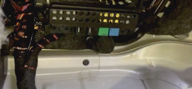
Relay box
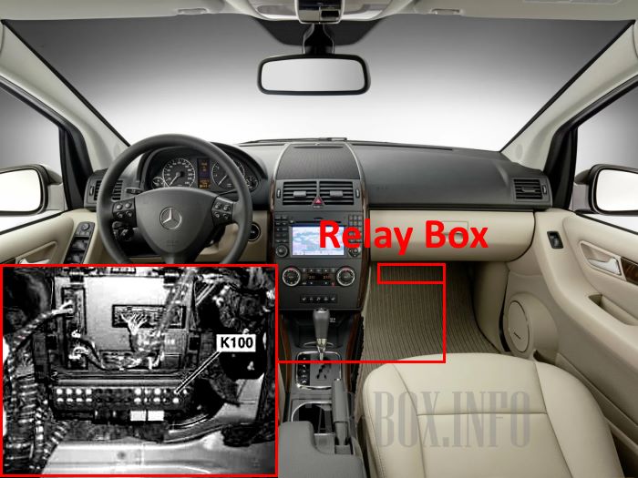
Located behind the passenger side trim (K100). For access:
For access:
1. Remove the trim under the glove compartment.
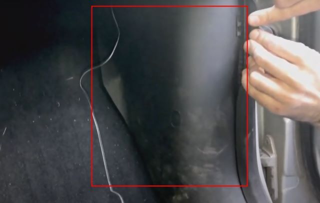
2. Remove the panel near the door.
3. Move the floor trim aside.
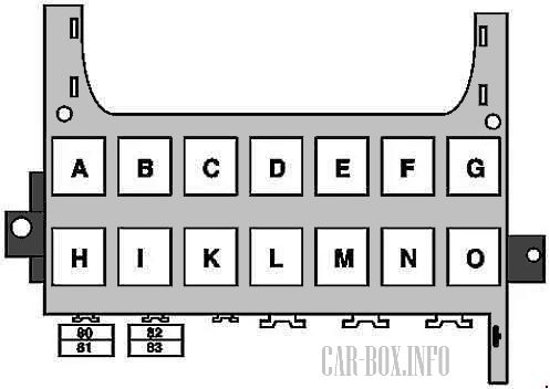
| K100 block diagram | ||
|---|---|---|
|
||
| No. | Relay description | |
| A | Circuit relay 15R (2) (SA) | |
| B | Circuit 15R relay (1) | |
| C | Horn relay | |
| D | rear window heating | |
| E | 1/2 wiper speed | |
| F | on / off wiper | |
| G | circuit 15 (1) | |
| H | Reserve | |
| I | Air pump | |
| K | Fuel module (fuel pump relay) | |
| L | Motor circuit relay 87 | |
| M | Starter | |
| N | circuit 87F | |
| O | Circuit 15 (2) (SA: xenon, cell phone) | |
| No. | Appointment | A |
| 80 | Cab | 30 |
| 81 | 30 | |
| 82 | 30 | |
| 83 | 30 | |
All electrical equipment
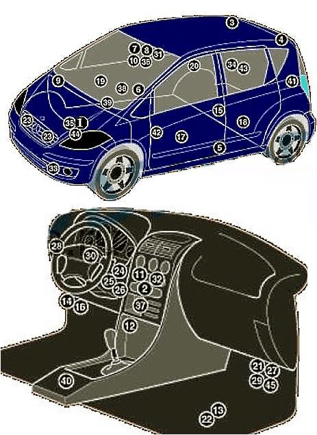
General layout of the electrical system in the vehicle.
1. ABS module;
2. Air conditioner control unit in the heater control panel;
3, 4. Antenna signal amplifiers;
5. Left impact sensor;
6. Right impact sensor;
7. Anti-theft system control module;
8. Vehicle tilt sensor (anti-theft system);
9. Anti-theft alarm system horn on the intake system resonator;
10. Volume change sensors (anti-theft system);
11. Audio system;
12. Auxiliary heater;
13. BATTERY;
14. CAN data bus, gateway control unit;
15. Central locking signal sensor (infrared) - in driver's door handle;
16. Diagnostic connector (DLC);
17. Left front door module;
18. Left rear door module;
19. Right front door module;
20. Right rear door module;
21. Relay box in the instrument panel;
22. Fuse box, in the footwell;
23. Klaxon behind front bumper;
24. Ignition switch control module;
25. Immobilizer- (integrated with ignition switch control module);
26. immobilizer antenna;
27. Turn signal/emergency signaling relay in the multifunction control unit;
28. Lighting unit;
29. Multifunction control module-connected to fuse/relay box in footwell -functions: Interior light bulbs, exterior light bulbs, horn, windshield wipers, central locking, power windows, turn indicators, anti-theft system, sunroof, seat heaters, immobilizer;
30. Multifunction control on steering wheel;
31. Multifunction switch control unit;
32. Navigation module;
33. Outside temperature sensor;
34. Parktronic module;
35. Power steering control unit;
36. Rain sensor - in the interior rearview mirror;
37. Seat heating module;
38. Seat occupant sensor;
39. Steering column electrical control unit;
40. SRS system;
41. Telephone network connection module;
42. Telephone interface;
43. Trailer electrical system;
44. Transmission module - in the gearbox;
45. Intermittent windshield wiper relay.

It's a good application and facilitates easy