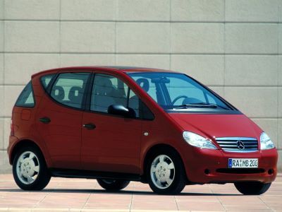
The first generation of the A-Class was introduced in the fall of 1997. Mercedes W168 was a very unusual model in the company's lineup: in addition to an unusually short body, it was equipped with front-wheel drive. Another feature was the system of frontal impact absorption (the so-called "sandwich"). In this article, we will take a detailed look at the fuse box diagrams for the Mercedes A-Class W168 (1st Gen; A140, A150, A160, A170, A180, A190, A200 and A210) 1997, 1998, 1999, 2000, 2001, 2002, 2003, 2004 years of manufacture.
Here you will find the locations and photos of distribution boxes. The fuses responsible for the “Cigarette lighter” and “Fuel Pump” are highlighted in bold.
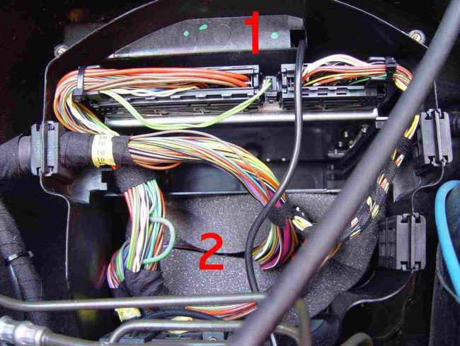
In the passenger compartment
There are two distribution boxes here that are responsible for protecting the electrical circuits.
Primary fuse box
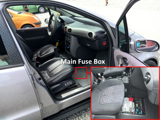
Located on the front passenger side under the cover in the footwell.
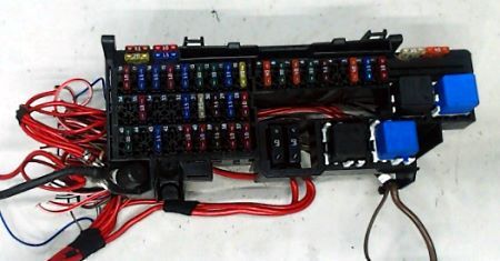
General view of the Mercedes A-Class W168 fuse box.
| Diagram | ||
|---|---|---|
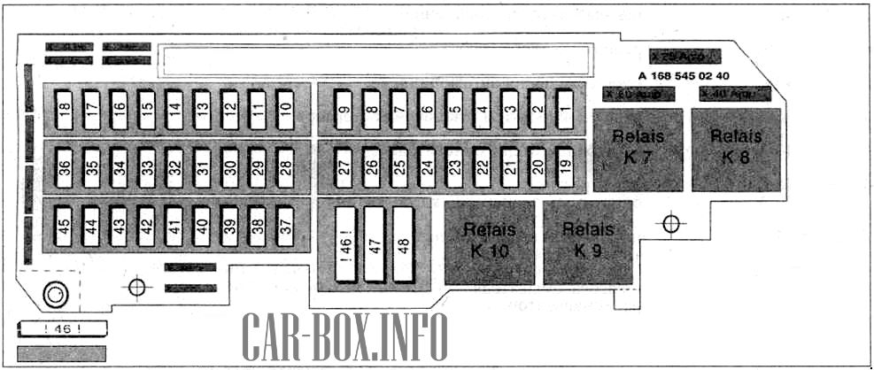
|
||
| No. | Description | A |
| 1 | fuel tank vent valve | 20, 10 diesel |
| fan relay | ||
| fuel injection control unit | ||
| idle speed control unit | ||
| EGR valve | ||
| lambda probe heater 1 | ||
| lambda probe heater 2 | ||
| diagnostic connector | ||
| [tempomat] | ||
| relay and boost valve. USA models | ||
| fuel shutoff valve | ||
| fan relay diesel power control unit | 10 (diesel) | |
| diaphragm valve | ||
| throttle valve | ||
| EGR valve | ||
| catalyst temperature sensor | ||
| 2 | ignition coil engine control unit | 25 (diesel) |
| fuel injectors | ||
| fuel pump fuse | ||
| electronic accelerator | ||
| starter blocking and shutdown relay | ||
| 3 | radiator blower [with air conditioner] | 30, 40 |
| 4 | engine control module | 7.5 |
| 5 | automatic clutch | 40 |
| 6 | fuel pump relay | 30 |
| 7 | vehicle lighting module | 40 |
| 8 | starter blocking and shutdown relay | 30 |
| 9 | cleaner motor | 40 |
| 10 | electric sunroof | 40 |
| rear window wiper | 20 | |
| 11 | paddle switch: | 15 |
| - window cleaner | ||
| - horn (beep) | ||
| - washer pump | ||
| - radio navigator | ||
| - cigarette lighter fuse mercedes w168 | ||
| 12 | socket in the trunk radio, glove compartment light, CD changer | 30 |
| 13 | front window elevator | 30 |
| power windows on all doors | 7.5 | |
| 14 | instrument panel (clock) purifier and washer relay [mobile phone] | 10 |
| 15 | safety airbag unit | 10 |
| child seat recognition unit | ||
| [side airbag sensor] | ||
| 16 | exterior mirror drive and mirror heater [parking assist] | 15 |
| 17 | horn (beep) | 15 |
| 18 | instrument panel | 10 |
| Transponder and remote control signal receiver | ||
| electronic engine control unit relay | ||
| 19 | coupling device | 30 |
| 20 | 15 | |
| 21 | 15 | |
| 22 | audio system | 25 |
| 23 | No | |
| 24 | No | |
| 25 | No | |
| 26 | No | |
| 27 | No | |
| 28 | instrument panel | 10 |
| [power windows] | ||
| 29 | central locking system | 15 |
| seat position recognition unit | ||
| 30 | transponder and signal receiver from the remote control | 7.5 |
| electronic instrument panel | ||
| 31 | heated rear window | 25 |
| 32 | [mobile phone] | 15 |
| [radio receiver or radio navigation system] | ||
| [CD changer] | ||
| interior lamps | ||
| 33 | power windows | 30 |
| 34 | fuel filter heater or supercharger. U.S. models | 30/40 |
| 35 | [alarm control unit] | 10 |
| light and sound signaling relays | ||
| 36 | heated front seats | 25 |
| 37 | [program selector] | 10 |
| coolant heater relay | ||
| 38 | air conditioning compressor | 10 |
| air mixing flap motor | ||
| cabin air temperature sensor | ||
| washer fluid heater | ||
| 39 | lighting module | 7.5 |
| tail light | ||
| 40 | stop lamps | 10 |
| 41 | air conditioning compressor, diagnostic connector | 10 |
| 42 | window elevators | 30 |
| 43 | ESP brake light switch | 15 |
| 44 | transmission control unit or automatic clutch | 10 |
| 45 | interior heater or [air conditioner] fan | 30 |
| 46 | onboard network | 80 |
| 47 | power steering pump | 60 |
| 48 | preheating control unit. | 60 |
| Diesel vehicles | ||
| No. | Relay assignment | |
| K7 | Mercedes W168 fuel pump relay | |
| K8 | fuel system control unit and ignition relay ESP / VGS or ESP / automatic transmission. | |
| K9 | VGS = transmission control unit | |
| K10 | rear window heating | |
Additional fuse box
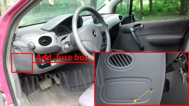
Located near the headlight switches on the side of the dashboard.
| Diagram | ||
|---|---|---|

|
||
| No. | Appointment | A |
| 1 | Left headlight - dipped beam | 7.5 |
| 2 | Right headlight - dipped beam | 7.5 |
| 3 | Headlamp-high beam, headlamp high beam indicator | 15 |
| 4 | Front left parking light/rear left parking light bulbs | 7.5 |
| 5 | Front/rear parking lamps (right), license plate illumination lamps, instrument panel illumination lamps | 15 |
| 6 | Fog lights | 15 |
In the engine compartment
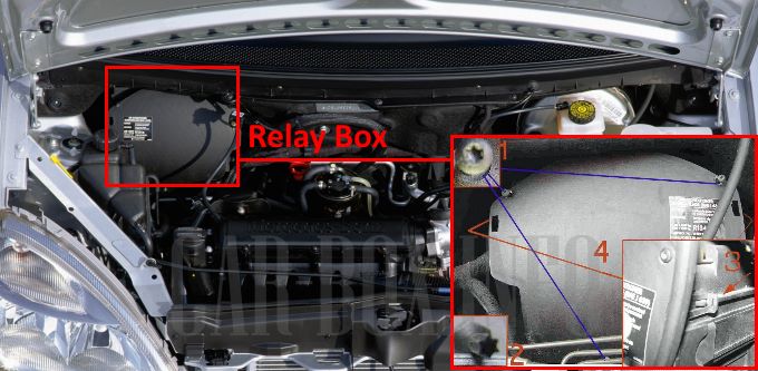
The block with relay modules is located on the right side under the plastic cover. To access its elements, unscrew the three fixing screws, press the clips and remove the cover.
Access example.
| Diagram | |
|---|---|
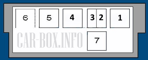
|
|
| No. | Description |
| 1 | Windshield washer pump |
| 2 | Horn (beep) |
| 3 | Prohibiting the activation of brake lights |
| 4 | Start prohibition relay |
| 5 | cooling fan |
| 6 | ABS / ESP pump |
| 7 | Exhaust air system pump (gasoline) |
All electrical equipment
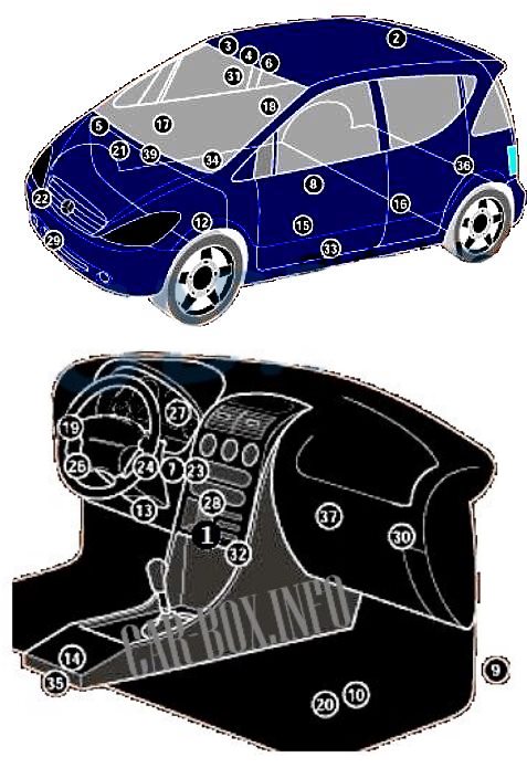
General layout of electrical equipment in mercedes w168.
1. Air conditioner control module in the heater control panel;
2. Antenna signal amplifier;
3. Anti-theft system control module - interior light bulbs;
4. Vehicle tilt sensor (anti-theft system) - in the anti-theft system control unit;
5. Anti-theft system horn;
6. Volume change sensors (anti-theft system) - in the anti-theft system control unit;
7. Anti-theft system signal control unit - in the immobilizer control unit;
9. Receiver for remote control of the auxiliary heater;
10. Passenger-side footwell battery pack;
12. Clutch actuator control module;
13. Diagnostic connector (DLC);
14. Power window control module in the front window control panel;
15. Left front power window control module - in the power window motor;
16. Left rear window control module - in the power window motor;
17. Right front window control module - in the power window motor;
18. Right rear window control module - in the power window motor;
19. Dashboard fuse box;
20. Main fuse/relay box, footwell;
21. Relay box, engine compartment;
22. Horn - behind front bumper;
23. Immobilizer control unit;
24. Immobilizer ring antenna - near ignition switch;
26. Lighting control module-in the headlight switch;
27. Multifunction control unit-Functions: Central locking, turn indicators, sunroof-in the instrument cluster;
28. Navigation system control unit-in the audio system unit;
29. Air temperature sensor;
30. Parktronic control unit;
31. Rain sensor - in the inside rear view mirror;
32. Seat heating control unit - in the switch unit;
33. left Side impact sensor,;
34. right side impact sensor;
35. SRS module;
36. Telephone network connection module;
37. Telephone interface control unit;
39. Intermittent windshield wiper relay - windshield wiper motor.
